Ejection seat pan lifter

a technology of ejection seat and pan lifter, which is applied in the direction of aircraft ejection means, movable seats, transportation and packaging, etc., can solve the problems of inconvenient use, small female pilots, and insufficient upward travel of existing seats

Active Publication Date: 2015-02-26
AMI INDS
View PDF16 Cites 7 Cited by
  • Summary
  • Abstract
  • Description
  • Claims
  • Application Information

AI Technical Summary

Problems solved by technology

While, in some cases, existing seats can be maneuvered for pilot comfort, it is often the case that the existing seats cannot travel upward enough to handle the new, smaller female pilots.
These cushions have to be stored separately, however, which makes their use inconvenient.

Method used


Image

  • Ejection seat pan lifter
  • Ejection seat pan lifter
  • Ejection seat pan lifter

Examples


Embodiment Construction

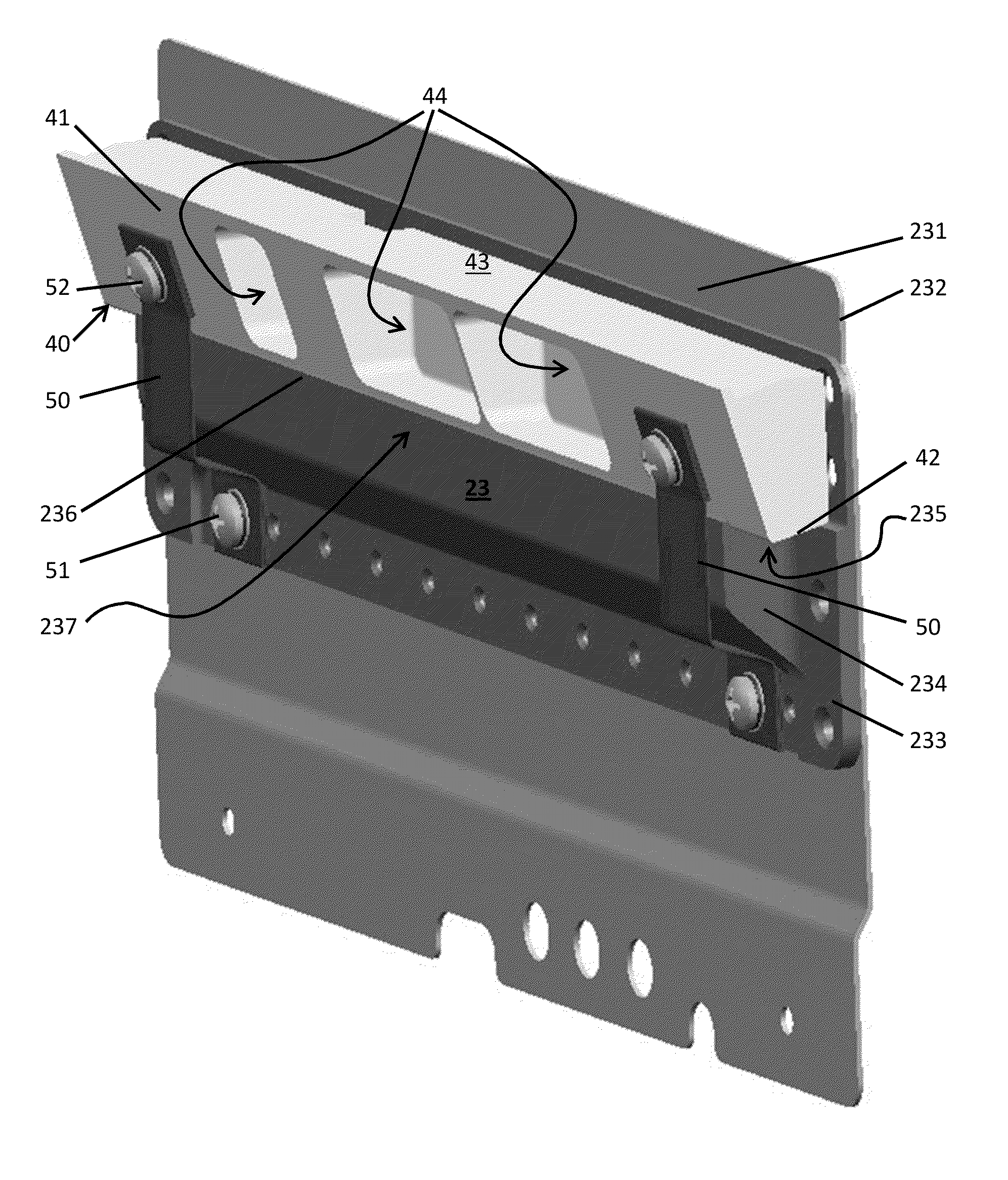
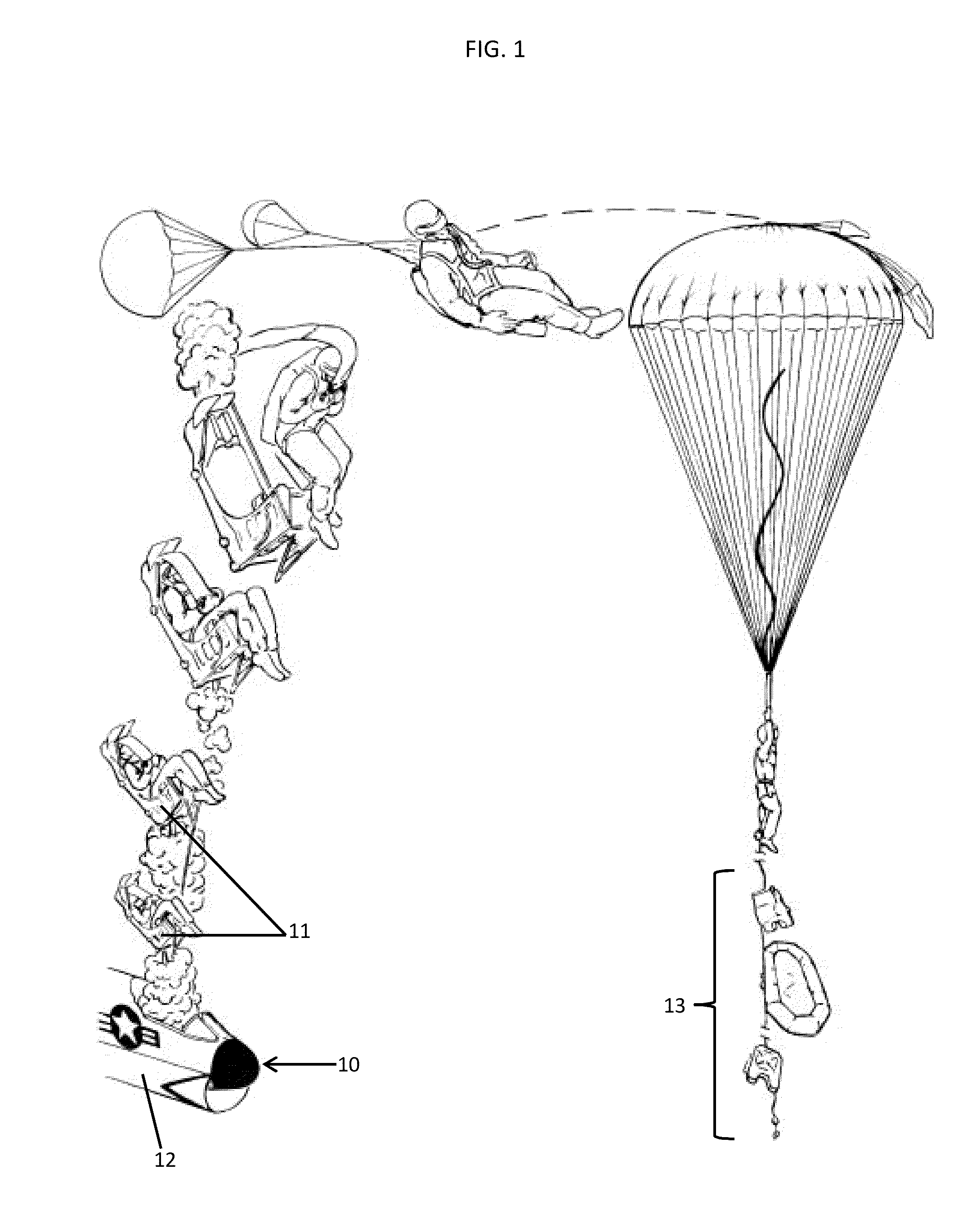
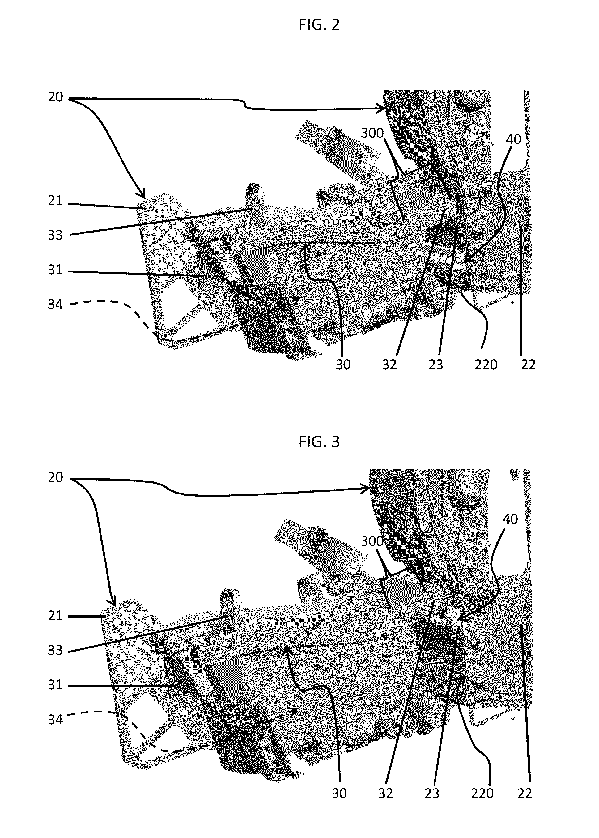
[0014]Most aircraft ejection seats, such as those found in military aircraft, have a seat pan that hinges in the front of the seat and is held up on a ledge in the back. The survival kit may be stored underneath this seat pan. In accordance with aspects, a block spacer is installed on the ledge to accommodate extra small pilots or aircraft occupants. When not in use, this block spacer is stored next to the survival kit and should be retained so it will not come free during ejection procedures and become a hazard. The additional height adjustment occurs as a result of the block spacer being interposed between the ledge and the seat pan and effectively tilting the seat pan about the hinge to lift the seat pan. The block spacer can therefore be used to lift a relatively small pilot or occupant an inch or two when the existing seat pan geometry does not otherwise allow for such an adjustment. Thus, since smaller pilots or occupants will be able to fit into the aircraft, the aircraft wil...


PUM


Abstract

An aircraft is provided and includes a fixed frame including a ledge and a seat pan on which seating elements for seating an aircraft crewperson are disposable. The seat pan includes a hinge about which the seat pan is pivotable relative to the fixed frame and a flange disposable on the ledge to establish a first pivot position for the seat pan relative to the fixed frame and a seat pan lifter coupled to the fixed frame and selectively interposable between the flange and the ledge to establish a second pivot position for the seat pan relative to the fixed frame.

Description

BACKGROUND OF THE INVENTION[0001]The subject matter disclosed herein relates to an ejection seat of an aircraft and, more particularly, to a pan lifter of an ejection seat of an aircraft.[0002]Aircraft, such as modern military aircraft, are often required to accommodate smaller pilots than the cockpits were designed to fit. This is partially due to an increase in the number of female pilots being in service and the fact that female pilots tend to be smaller than their male counterparts. While, in some cases, existing seats can be maneuvered for pilot comfort, it is often the case that the existing seats cannot travel upward enough to handle the new, smaller female pilots. Indeed, for some pilots, there may be a need for several inches of adjustment.[0003]Presently, there are options for cushions that can be attached to the seat pan to raise the smaller pilots up. These cushions have to be stored separately, however, which makes their use inconvenient. Consequently, they are rarely u...

Claims


Application Information

Patent Timeline
Patent Type & Authority Applications(United States)
IPC IPC(8): B64D25/10
CPCB64D25/10
Inventor MASTROLIA, BRADLEYHAMPTON, JOHNTULLOCH, JAMESOCHS, JEREMY
Owner AMI INDS
Why Eureka
Try Eureka