
System and method for providing traffic information

Active Publication Date: 2015-02-26
KOSATKA PIORO ALEKSANDRA
View PDF11 Cites 6 Cited by
  • Summary
  • Abstract
  • Description
  • Claims
  • Application Information

AI Technical Summary

Benefits of technology

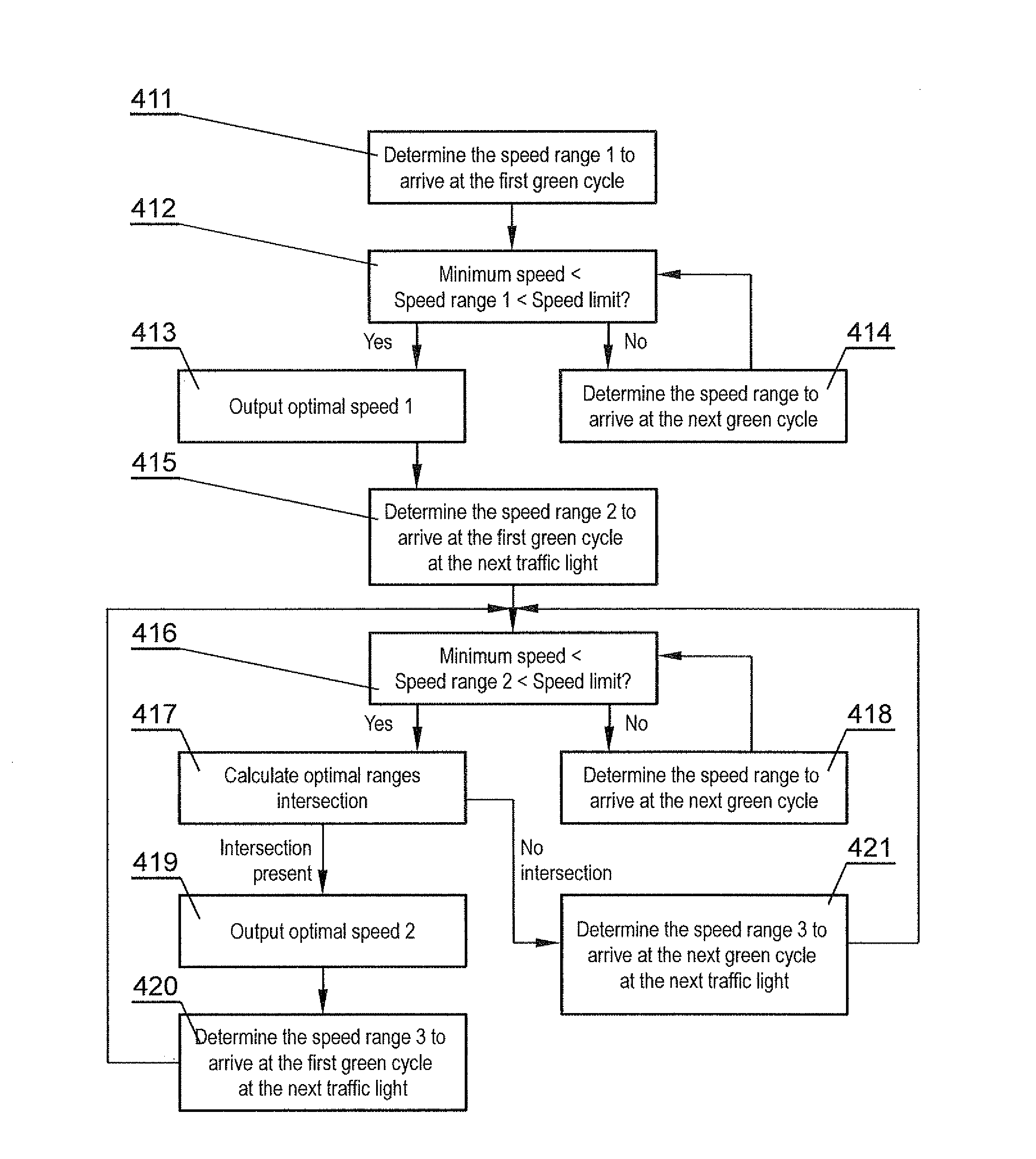
The patent describes a computer-implemented method for providing traffic information to a moving vehicle through a navigation module. The method involves obtaining geolocalization data of the vehicle, identifying the closest traffic light, retrieving operational information on the identified traffic light, processing the information to determine an optimal speed at which the vehicle should move to arrive at the closest traffic light when it is at green phase, and outputting the optimal speed via the user interface of the navigation module. The optimal speed is determined based on factors such as speed range and speed limit, and the speed limit may be determined based on the type of vehicle or the road region between the vehicle and the closest traffic light. The method may be operated cyclically and may be performed using computer software or a computer program. The navigation module used for providing traffic information to the vehicle includes a geolocalization module, a mapping system, a data interface, a data processor, and a user interface.

Problems solved by technology

Traffic congestion is a well-known problem, especially in cities with a high number of crossroads.
Traffic flow may be optimized by providing systems for management of traffic lights, but these systems have a reactive nature—they may adapt the traffic light to actual traffic conditions, but have limited capabilities of impacting individual vehicles to optimize their movement.
The drawback of this system is that each driver shall maintain a particular optimal speed, for example 50 km / h, on the particular section of the road.
However, in traffic conditions, a driver must adapt to other vehicles, which often means that it will not be possible to maintain the optimal speed in order to keep with the green wave.
The drawback of the system is that it requires the driver to make own assessments and that it is effective only within the range of the eyesight of the driver.

Method used


Image

  • System and method for providing traffic information
  • System and method for providing traffic information
  • System and method for providing traffic information

Examples


Embodiment Construction

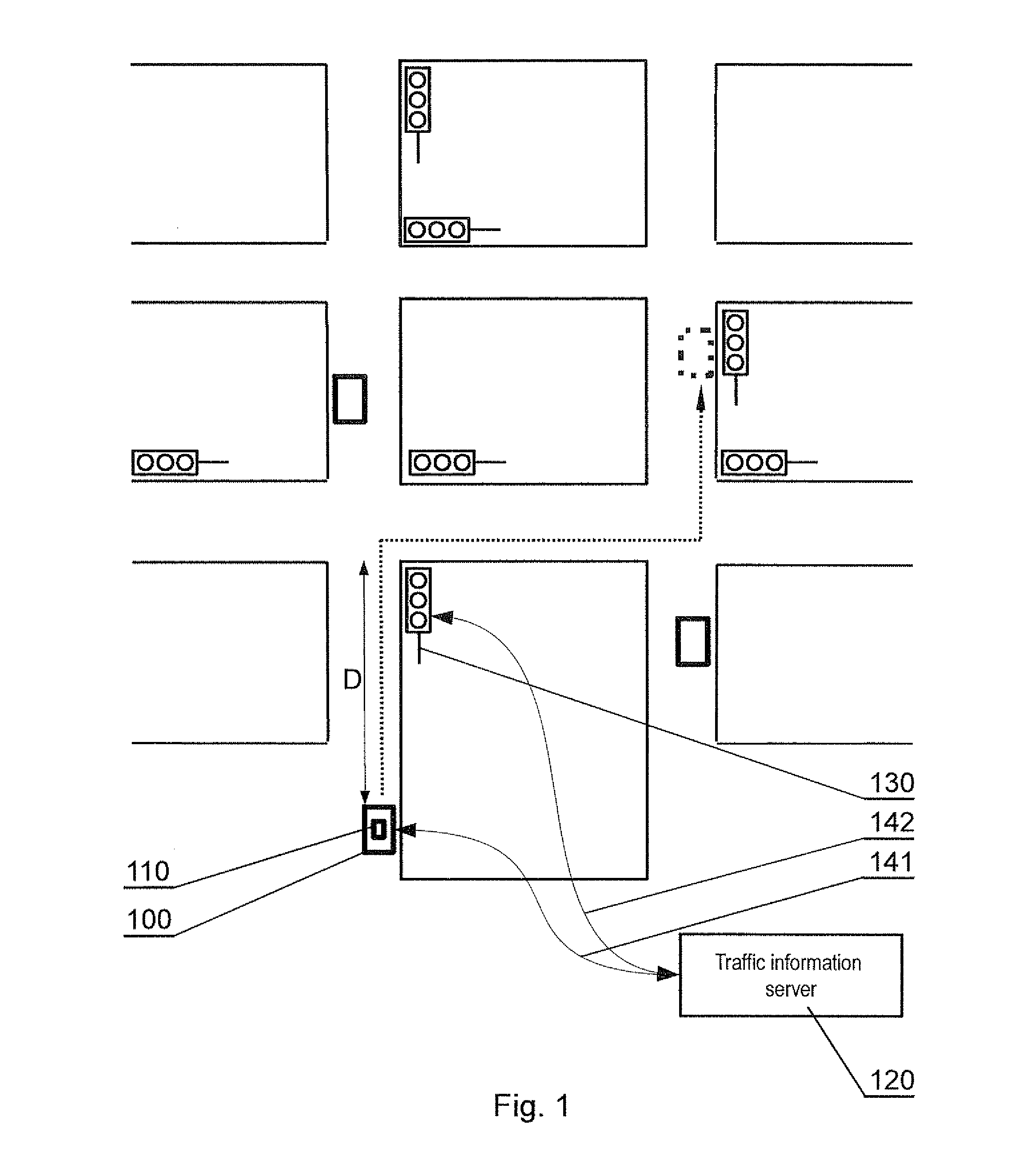
[0026]FIG. 1 shows an exemplary traffic situation, wherein a vehicle approaches a traffic light 130 and is currently at a distance D from that traffic light. Vehicles which use the system are equipped with navigation modules 110, which communicate with a traffic information server 120, wherein the server 120 also communicates with the traffic lights 130.

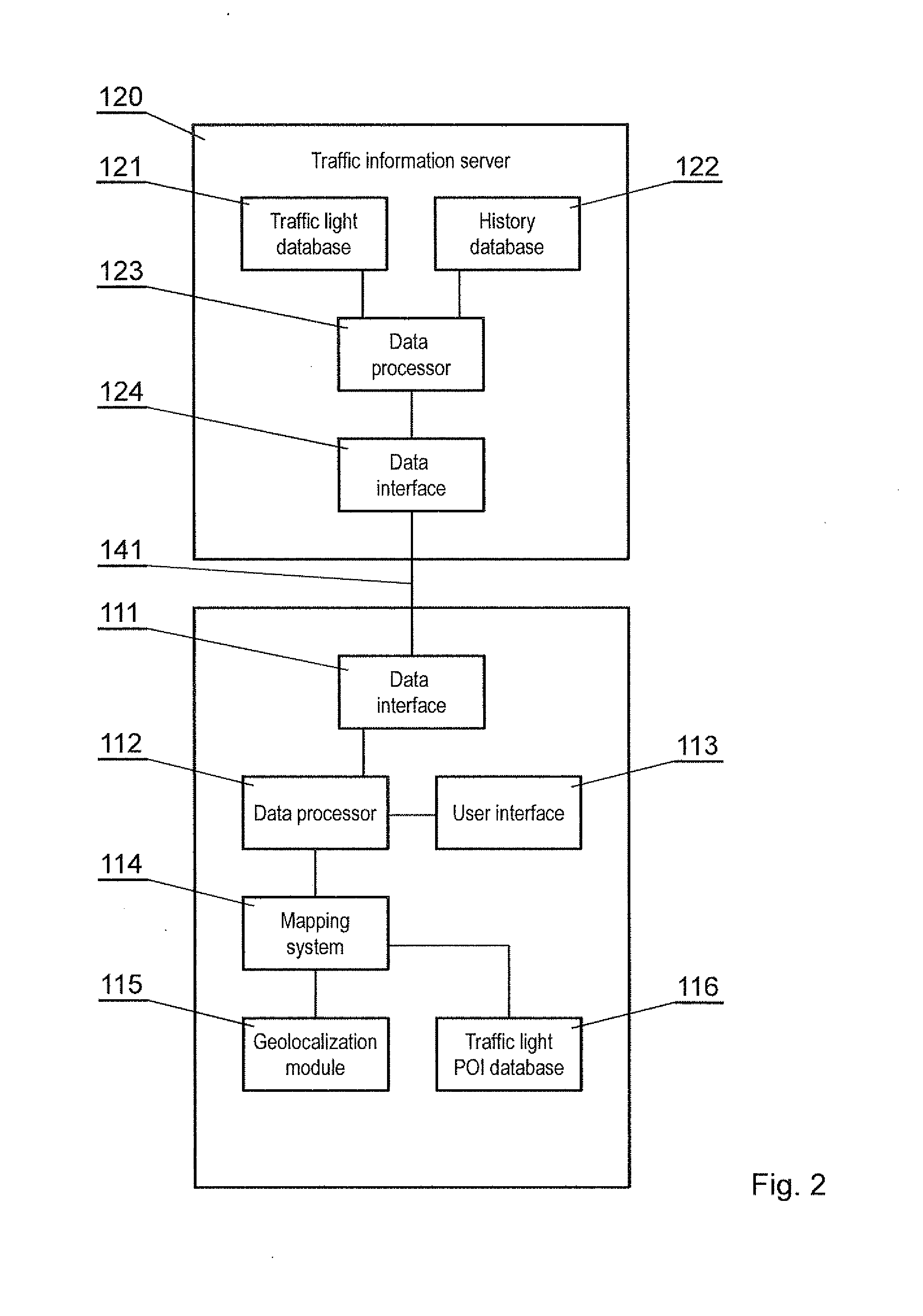
[0027]FIG. 2 presents a diagram of the components of the system.

[0028]The traffic information server 120 comprises a traffic lights database 121, which stores, for each traffic light 130 handled by the system, information about light cycle. The content of the information about the light cycle may be dependent on the particular traffic lights management system used. For static systems, the information may include a list of light change times. For adaptive systems, the information may include only information about the next expected light change only, as the light may be operated adaptively to road conditions. The database 121 may also...


PUM


Abstract

A computer-implemented method for providing traffic information via a navigation module onboard a moving vehicle, comprising the steps of: obtaining geolocalization data of the vehicle; identifying the closest traffic light ahead the vehicle; retrieving, from a remote traffic light server, operational information on the identified closest traffic light; processing the operational information to determine an optimal speed at which the vehicle should move to arrive at the closest traffic light when it is at green phase; and outputting the optimal speed via a user interface of the navigation module.

Description

BACKGROUND OF THE INVENTION[0001]1. Field of the Invention[0002]The object of the present invention is a system and a method for providing traffic information, in order to reduce traffic, optimize travel time and increase safety, especially within city limits.[0003]2. Description of the Related Art[0004]Traffic congestion is a well-known problem, especially in cities with a high number of crossroads. Traffic flow may be optimized by providing systems for management of traffic lights, but these systems have a reactive nature—they may adapt the traffic light to actual traffic conditions, but have limited capabilities of impacting individual vehicles to optimize their movement.[0005]Traffic management systems may be configured as a so-called ‘green wave’, where the main road has traffic lights configured such that a vehicle moving at a certain speed, for example 50 km / h, will reach the next traffic lights at a green light. The drawback of this system is that each driver shall maintain ...

Claims


Application Information

Patent Timeline
IPC IPC(8): G08G1/0967G08G1/0962
CPCG08G1/0967G08G1/096783G08G1/0962G08G1/096G08G1/09626G08G1/096716G08G1/096741G08G1/09675G08G1/096775
Inventor KOSATKA-PIORO, ALEKSANDRAPIORO, KRZYSZTOF
Owner KOSATKA PIORO ALEKSANDRA
Learn More