Liquid ejecting head and liquid ejecting apparatus

a liquid ejecting head and liquid ejecting technology, applied in the direction of printing, inking apparatus, etc., can solve the problems of ink discharging failure, flow-path resistance, problem or failure, etc., and achieve the effect of reducing the siz

Active Publication Date: 2015-02-26
SEIKO EPSON CORP
View PDF1 Cites 2 Cited by
  • Summary
  • Abstract
  • Description
  • Claims
  • Application Information

AI Technical Summary

Benefits of technology

[0017]It is possible to realize a liquid ejecting apparatus which c

Problems solved by technology

As a result, a problem or failure, such as an ink discharging failure, may occur.
Furthermore, when an opening of the groove flow path is small, a flow-path resistance is caused and the path is choked by the air bubble.
Thus, there is a possibility that an ink supply failure may occur.
Providing fo

Method used


Image

  • Liquid ejecting head and liquid ejecting apparatus
  • Liquid ejecting head and liquid ejecting apparatus
  • Liquid ejecting head and liquid ejecting apparatus

Examples


Embodiment Construction

[0027]Hereinafter, detail of embodiments of the invention will be described.

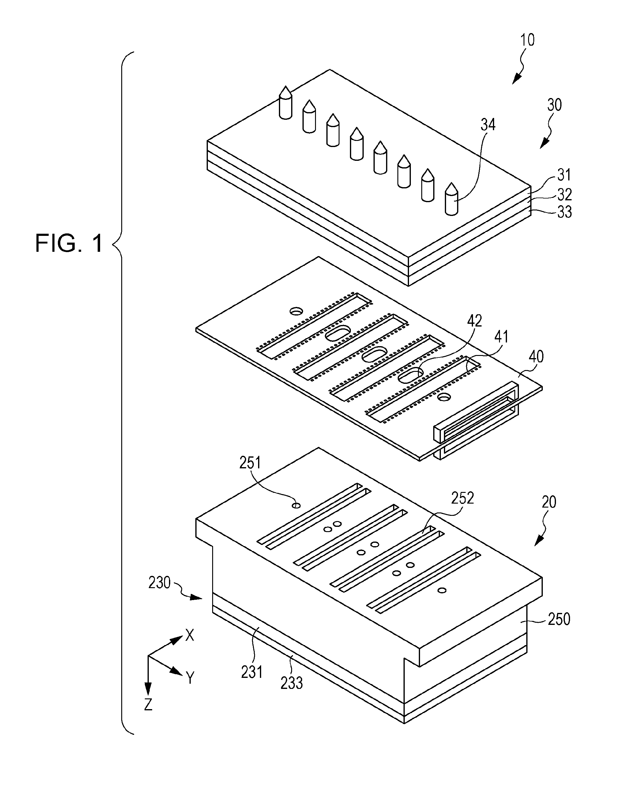
[0028]FIG. 1 is an exploded perspective view illustrating an ink jet type recording head as an example of a liquid ejecting head

[0029]An ink jet type recording head 10 may include a head main body 20 which can eject a liquid such as ink droplets, a flow-path member 30 which supplies ink to the head main body 20, and a wiring substrate 40 which is held between the head main body 20 and the flow-path member 30, as illustrated in FIG. 1.

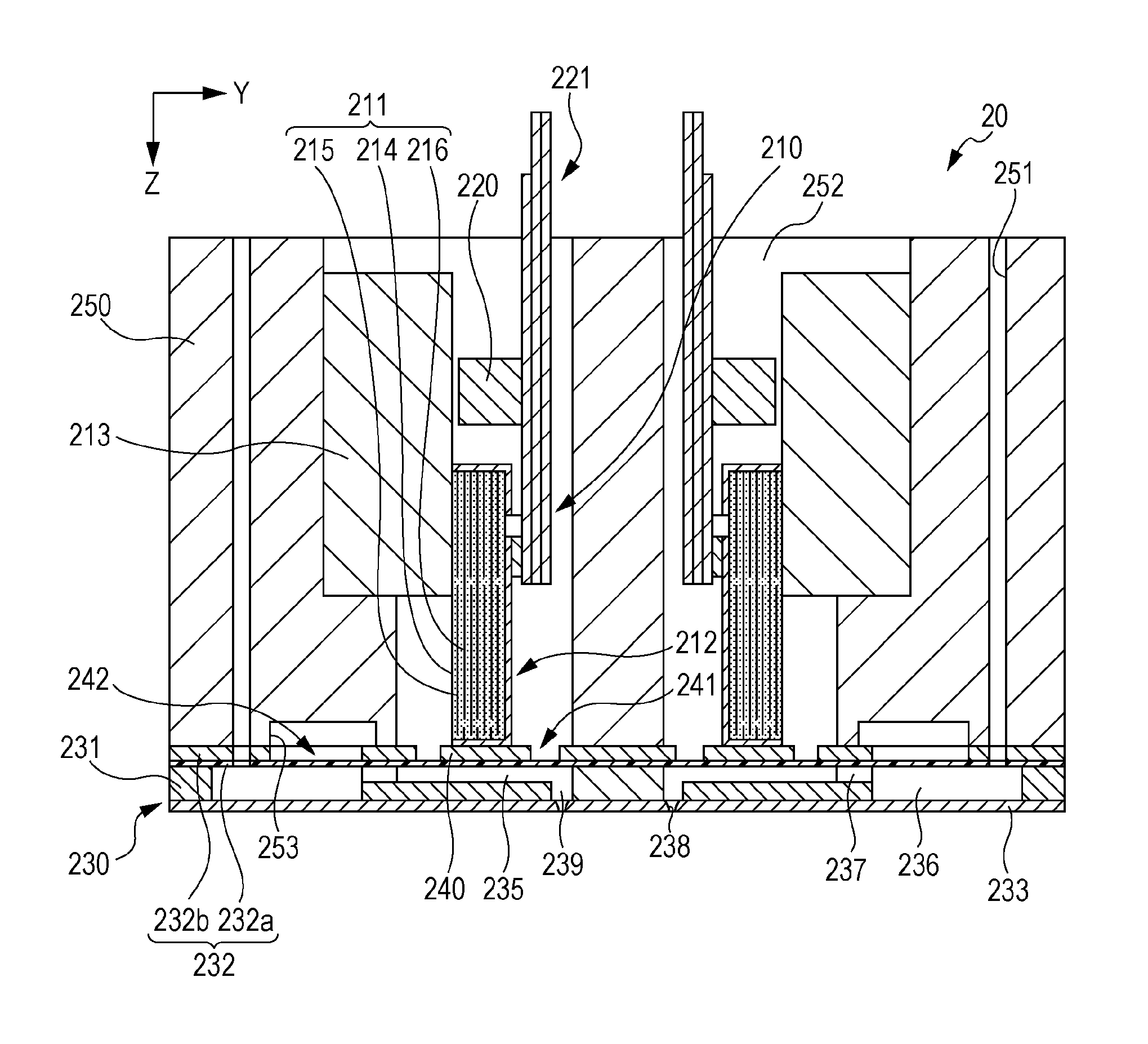
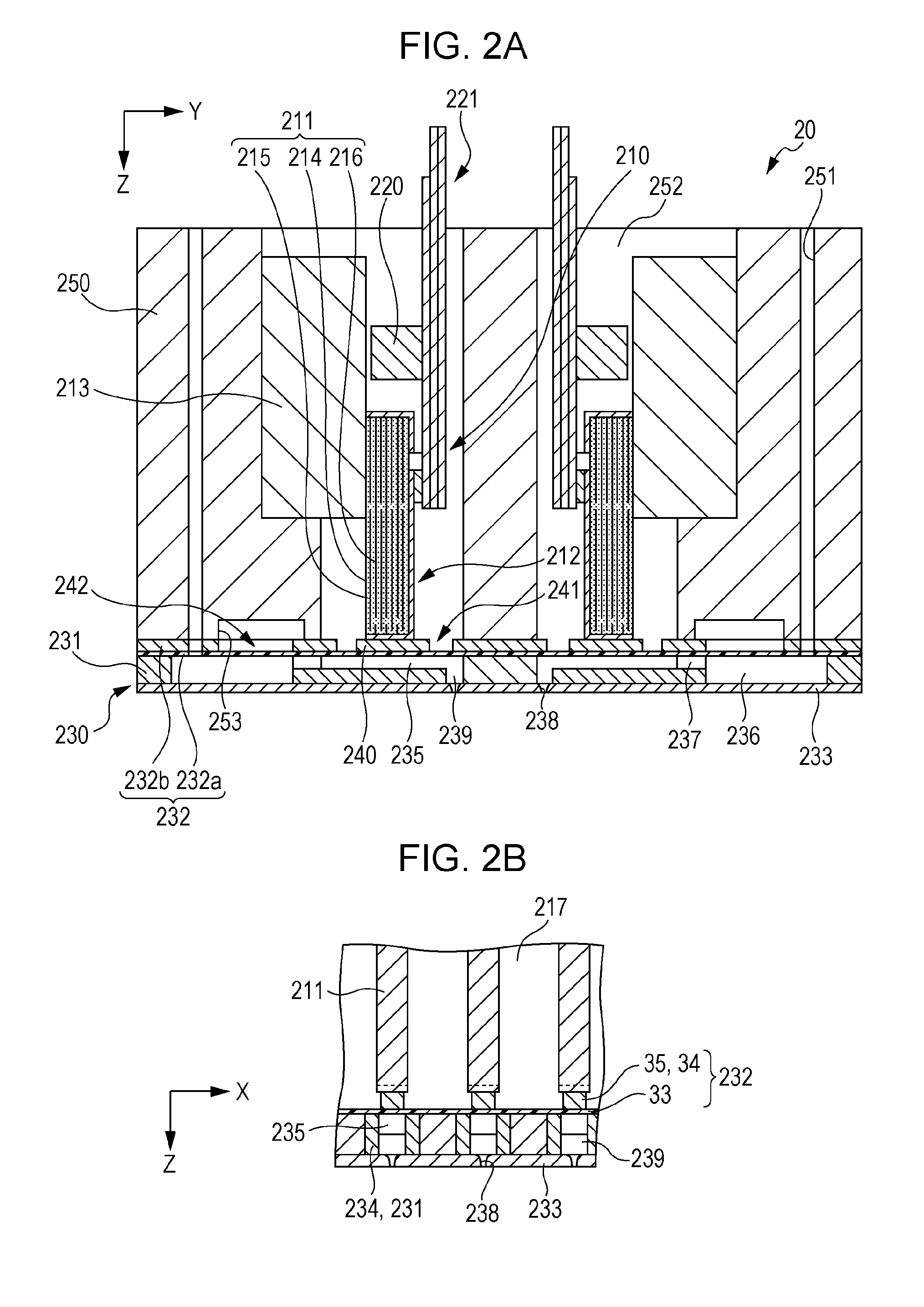
[0030]Detail of the head main body 20 will be described with reference to FIGS. 2A and 2B. FIGS. 2A and 2B are cross-sectional views of principal portions of the head main body.

[0031]The head main body 20 may include a plurality of actuator units 210, a case 250 in which the actuator units 210 can be accommodated, and a flow path unit 230 which is adhered to one surface of the case 250, as illustrated in FIGS. 2A and 2B.

[0032]The actuator unit 210 may include a piezoelectric act...


PUM


Abstract

A liquid ejecting head may include a first flow path, a linking flow path that is provided on a downstream side of the first flow path and is connected to the first flow path, and a second flow path that is connected to the linking flow path. The first flow path, the linking flow path, and the second flow path are provided in a portion between a liquid receiving portion and a filter. The second flow path includes wall portions that partition a central flow path and external flow paths which are provided on both external sides of the central flow path. The linking flow path includes an inclined portion which is formed in a width direction and extends in a portion between the first flow path and the second flow path.

Description

CROSS REFERENCE TO RELATED APPLICATIONS[0001]The present application claims priority to Japanese Patent Application No. 2013-170800 filed on Aug. 20, 2013 which is hereby incorporated by reference in its entirety.BACKGROUND[0002]1. Technical Field[0003]Embodiments of the present invention relate to a liquid ejecting head which ejects liquid through nozzle openings and a liquid ejecting apparatus. More particularly, embodiments relate to an ink jet type recording head which discharges ink as liquid and an ink jet type recording apparatus.[0004]2. Related Art[0005]An ink jet type recording head which discharges ink droplets is a representative example of a liquid ejecting head which discharges liquid droplets. An ink jet type recording head that may include a head main body which discharges ink droplets through nozzle openings and a common flow-path member which allows ink sent from a liquid receiving portion to be supplied to each head main body has been proposed as an ink jet type r...

Claims


Application Information

Patent Timeline
IPC IPC(8): B41J2/14
CPCB41J2/1433B41J2/14233B41J2/175B41J2/17563B41J2/19B41J2202/11
Inventor KINOSHITA, RYOTA
Owner SEIKO EPSON CORP
Why Eureka
Try Eureka