Method And Tool For Measuring The Geometric Structure Of An Optical Component

Active Publication Date: 2015-02-26
ESSILOR INT CIE GEN DOPTIQUE
View PDF0 Cites 1 Cited by
  • Summary
  • Abstract
  • Description
  • Claims
  • Application Information

AI Technical Summary

Benefits of technology

[0019]Thus, the procedure according to the invention also presents the advantage of being able to be implemented on the basis of existing apparatuses configured to carry out measurements of faces but which do not comprise any calculation means for reconstructing these faces in a datum which is not tied to themselves.
[0020]A third advantage of the procedure according to the invention is related to the form in which the determination of the structure is produced: the steps of reconstructing the faces presented below employ a representation of the faces in an analytical form. Fu

Problems solved by technology

But the precision of the geometric structure reconstructed is not always satisfactory because each of the two measurements combines the effects of the two faces traversed.
But the duration of a measurement of a face is significant and it is still always difficult to position the measurement of the

Method used


Image

  • Method And Tool For Measuring The Geometric Structure Of An Optical Component
  • Method And Tool For Measuring The Geometric Structure Of An Optical Component
  • Method And Tool For Measuring The Geometric Structure Of An Optical Component

Examples


first embodiment

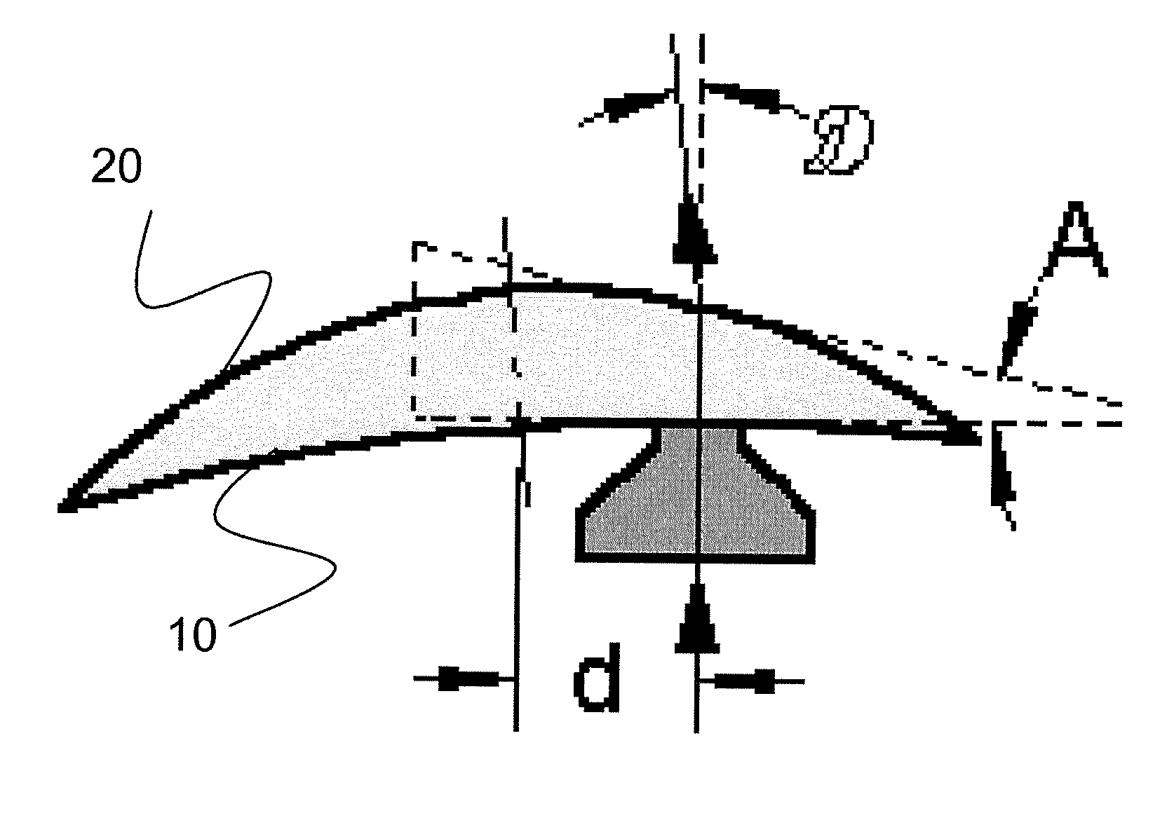
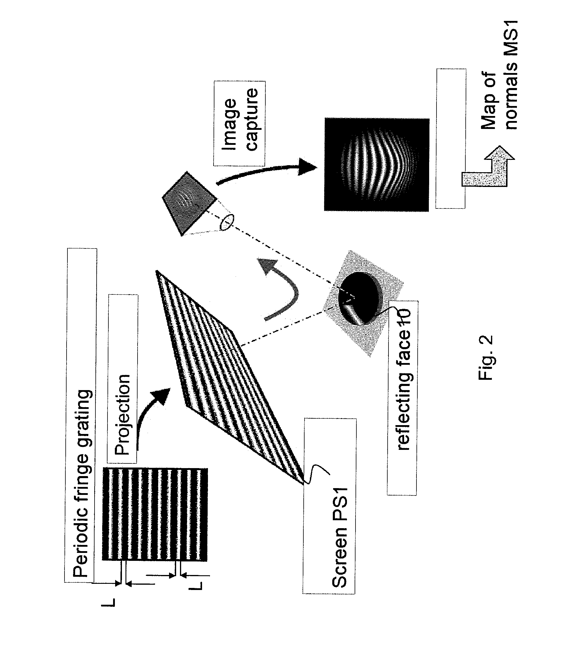
[0035]In a first embodiment, the first face 10 is illuminated by a fringe grating and the extent of this grating is greater than the size of the first face 10. Thus the zonal measurement makes it possible to measure the entirety of the face 10 in a single, fast and simple step.

[0036]Advantageously, the zonal measurement can be obtained by a collection of elementary zonal measurements carried out for example with a fringe grating as described above, illuminating only a fraction of the first surface that will be dubbed the “elementary zone”. The elementary zonal measurement measures the signal arising from the reflection of the fringe grating by the elementary zone. The elementary zonal measurements are repeated until the elementary zones cover the whole of the first face. The zonal measurement is obtained by joining up the various elementary zonal measurements.

second embodiment

[0037]An example of this second embodiment for a zonal measurement carried out on the basis of two elementary zonal measurements can be described as follows: the first face 10 is illuminated by a fringe grating whose extent is less than the total surface of the first face 10. Let us consider for example that the fringe grating covers 60% of the surface of the first face 10. A first elementary zonal measurement is carried out as indicated hereinabove on a first elementary zone Z1 corresponding to the 60% of the first face covered by the grating for a first position of the first face with respect to the grating. To measure the whole of the first face 10, said first face 10 is thereafter displaced with respect to the grating so that the latter is projected onto another portion of the face 10 and covers a second elementary zone Z2, for example a zone still covering 60% of the surface of the first face, but where the elementary zones Z1 and Z2 overlap over an area corresponding to 20% of...


PUM


Abstract

The subject of the present invention is a method and a system for measuring the geometric or optical structure of an optical component. In particular, the invention relates to a method for measuring the geometric structure of a component bounded by a first side (10) and a second side (20), said method comprising steps of: (S1) measuring a first signal (MS1) resulting from a first conversion of a first probe signal (PS1), by at least said first side (10); (S2) measuring a second signal (MS2) resulting from a second conversion of a second probe signal (PS2), by at least said second side (20); (S3) determining a third conversion making it possible to convert a first set of coordinates (R1) associated with the measurement of the first signal (MS1) to a second set of coordinates (R2) associated with the measurement of the second signal (MS2); (S10) estimating said first side (10) using the first signal (MS1), said first simulation and a first cost criterion (V1) quantifying a difference between the estimation (FS1) and the first signal (MS1); and (S20) estimating said second side (20) using the second signal (MS2), said second simulation, said third conversion and a second cost criterion (V2) quantifying a difference between the estimation (ES2) and the second signal (MS2).

Description

FIELD OF THE INVENTION[0001]The subject of the present invention is a method and a system for measuring the geometric or optical structure of an optical component.[0002]The method according to the invention makes it possible to measure in an absolute manner the two faces of an optical component. Absolute measurement is intended to mean a measurement which does not require any prior knowledge of the component except for its refractive index. The measurement of faces is susceptible of numerous industrial applications. It is in particular useful in the ophthalmic field for the checking or the measurement of ophthalmic lenses; in this case, the making of complex faces requires the simultaneous determination of hundreds of coefficients.BACKGROUND OF THE INVENTION[0003]This section is intended to introduce the reader to the diverse aspects of the art, which may be related to various aspects of the present invention which are described and / or claimed hereinbelow. This discussion is conside...

Claims


Application Information

Patent Timeline
IPC IPC(8): G01M11/02
CPCG01M11/025G01M11/0264G01M11/0271G01B11/25G01B11/24
Inventor GUEU, STEPHANELA VILLONNIERE, NICOLASMURADORE, FABIENLAKHOUA, ASMA
Owner ESSILOR INT CIE GEN DOPTIQUE
Why Eureka
Try Eureka