Method for producing screen print

Inactive Publication Date: 2008-09-18
NGK INSULATORS LTD
View PDF1 Cites 3 Cited by
  • Summary
  • Abstract
  • Description
  • Claims
  • Application Information

AI Technical Summary

Benefits of technology

[0031]According to the method for producing a screen print of the present invention, screen printing excellent in precision can be performed even on a large printing material having a large printing area and a screen print excellent in printing precision can be produced. Furthermore, according to the method for producing a screen print of the present invention, a screen print in which the degree of deviation in printing position is c

Problems solved by technology

However, a printing plate frame has some distortion, and hence it is difficult to make a completely flat screen stretched on the printing plate frame.
Moreover, since the distortion of the printing plate frame differs depending on the printing plate frame, the arranged patters of the openings on the screen stretched on the printing plate frame also delicately differ depending on the respective screen printing plates.
Therefore, there is a problem that when screen printing is carried out using a plurality of screen printing plates differing in arranged patterns of openings, the print patterns on the

Method used


Image

  • Method for producing screen print
  • Method for producing screen print
  • Method for producing screen print

Examples


Example

Example 1

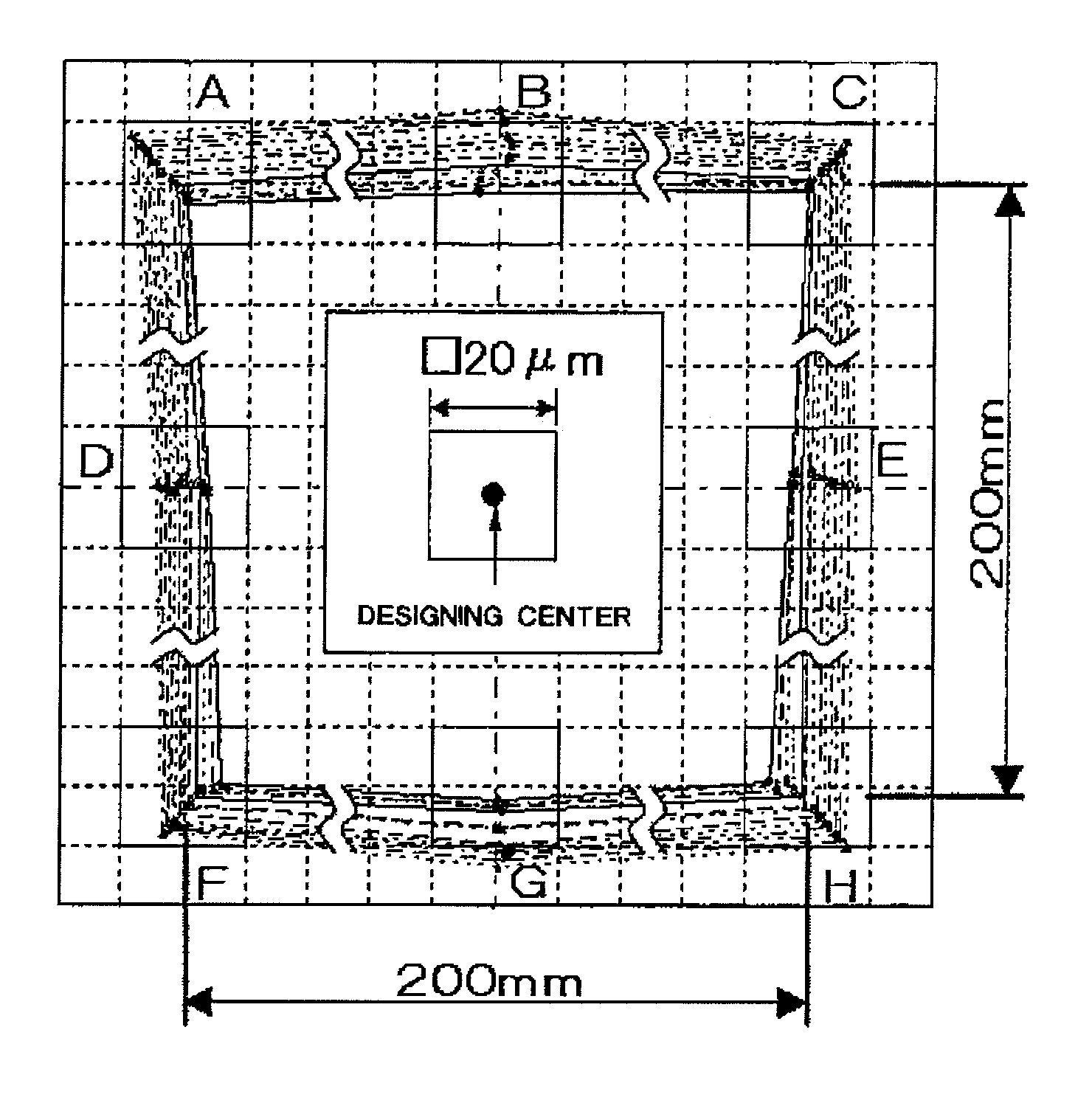
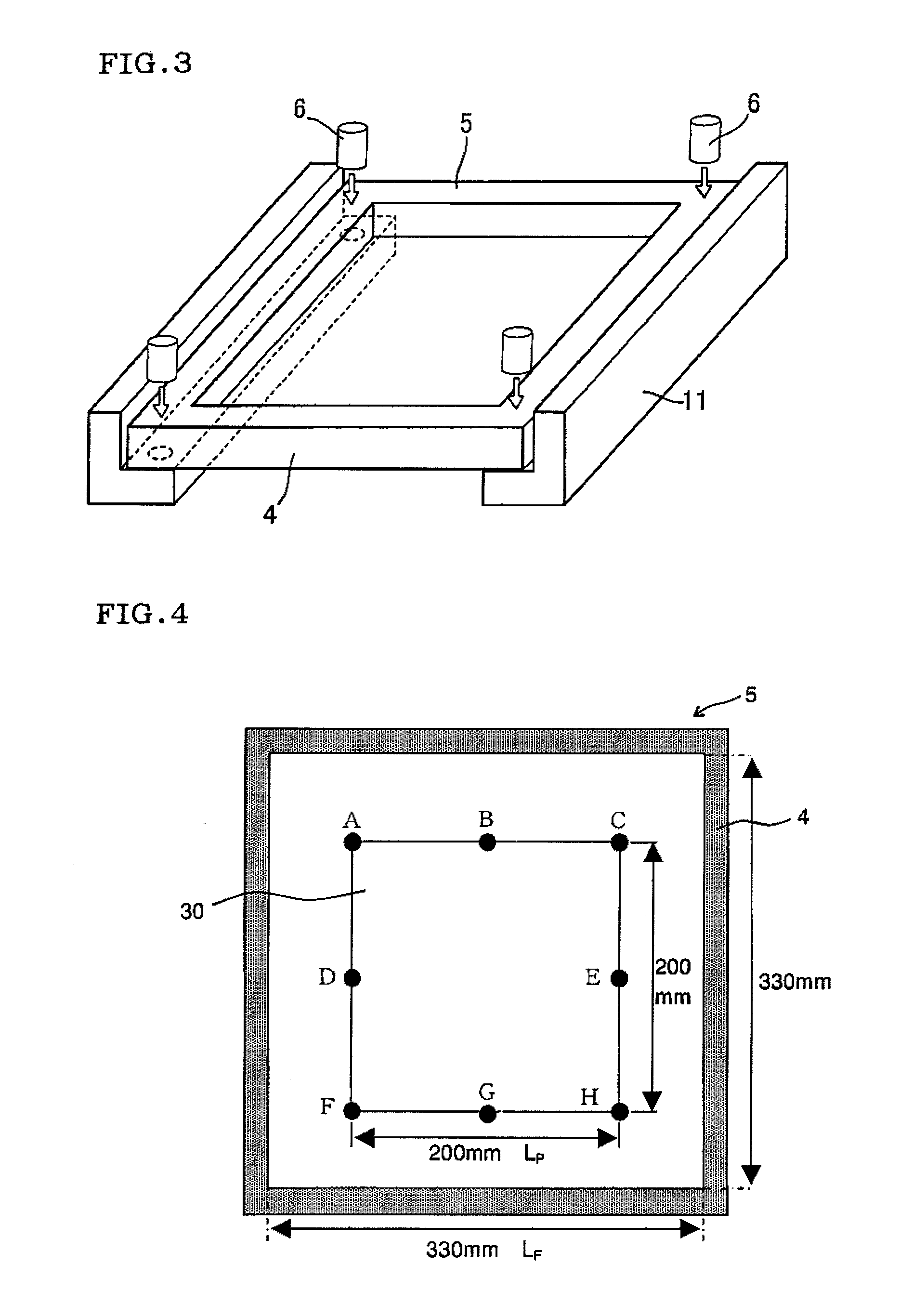
[0074]Using a screen printing plate 5 of 330 mm×330 mm in internal size as shown in FIG. 4 (manufactured by Murakami Co., Ltd., size of print pattern to be formed: 200 mm×200 mm), clearance was set at every 0.1 mm within the range of 0.3-1.5 mm, and test printing was conducted with the respective clearances to produce thirteen trial prints according to the first selecting and setting method. The degree of deviation in printing position of the resulting first trial prints (degree of deviation from designing center) was measured. FIGS. 5-7 show graphs prepared by plotting the results of measurement. The degree of deviation in printing position (mm) was plotted against the respective clearances (mm) set above to prepare calibration curves shown in FIG. 8. FIG. 8 shows calibration curve (1) in the case of approximating in the cubic function (y=−0.0352x3+0.086x2−0.049x+0.0044).

[0075]Using a screen printing plate which was the same in design specification (lot) as the screen prin...

Example

Example 2

[0076]Screen prints were produced in the same manner as in Example 1, except that screen printing plates of different lots were used. FIGS. 10-12 show graphs prepared by plotting the results of measurement of the degree of deviation in printing position of the resulting screen prints. In FIGS. 10-12, the point of plotting the results of measurement of the degree of deviation in printing position of the second trial print is shown by a black triangle.

Example

Example 3

[0077]Using a screen printing plate 5 of 330 mm×330 mm in internal size as shown in FIG. 4 (manufactured by Murakami Co., Ltd., size of print pattern to be formed: 200 mm×200 mm), clearance was set at 0.5 mm and 1.0 mm, and test printing was conducted with the respective clearances to produce two trial prints according to the second selecting and setting method, and the degree of deviation in printing position was measured. The degree of deviation in printing position (mm) was plotted against the respective clearances (mm) set above to prepare calibration curve (3) shown in FIG. 13.

[0078]From the intersection point of the degree of deviation in printing position=0 (mm) and the calibration curve (3), the optimum clearance (about 0.58 mm) for the screen printing plate used for producing the trial print according to the second selecting and setting method was read, and screen printing was carried out using the screen printing plate used hereinbefore as it was with setting the ...


PUM


Abstract

The method for producing a screen print having a given print pattern formed on a printing material by sliding a squeegee over a screen 3 of a screen printing plate comprising the screen 3 disposed above the printing material with keeping a given clearance C and a printing plate frame. The ratio (LP/LF) of a length (LP) of a side of the printing pattern perpendicular to axis of the sliding direction of the squeegee to an internal size (LF) of a side of the printing plate frame perpendicular to axis of the sliding direction of the squeegee is 0.45 or more, and an optimum clearance between the printing material and the screen printing plate is selected and set on the basis of correlation between the clearance CL (0.1-2 mm) and the degree of deviation in printing position of the print pattern.

Description

TECHNICAL FIELD[0001]The present invention relates to a method for producing a screen print excellent in printing precision.BACKGROUND ART[0002]Screen printing which forms a print film comprising ink, paste or the like on the surface of a material to be printed using a printing plate for screen printing (hereinafter sometimes referred to as merely “screen printing plate” or “printing plate”) can form fine patterns and has high mass-productivity, and hence is utilized in a wide variety of industrial fields. In general, screen printing is a method according to which using a screen mask constructed by stretching on a printing plate frame a mesh having openings closed with a resin (such as photosensitive emulsion film), an ink material is placed on the upper face of the screen mask and a squeegee is slid, thereby to squeeze out the ink material to the under side of the screen mask (substrate side) through the given openings formed in the screen mask to perform printing.[0003]According t...

Claims


Application Information

Patent Timeline
IPC IPC(8): B41M1/12
CPCB41M1/12H05K2203/163H05K3/1233H05K1/0306
Inventor OHMORI, MAKOTOAISAKA, YUKIOIDA, AYUMINANATAKI, TSUTOMU
Owner NGK INSULATORS LTD
Why Eureka
Try Eureka