
Outdoor combination floor

a combination floor and outdoor technology, applied in the field of outdoor floor coverings, can solve the problems of affecting the safety of pedestrians walking on the plank, affecting the safety of pedestrians, and wasting time, and achieve the effects of satisfying structural stability, quick and convenient lay, and enhancing pedestrian safety

Inactive Publication Date: 2015-03-05
NEXUS GLOBAL
View PDF11 Cites 39 Cited by
  • Summary
  • Abstract
  • Description
  • Claims
  • Application Information

AI Technical Summary

Benefits of technology

The present invention provides an outdoor floor covering that is easy to install and stays stable. It also helps to improve safety for pedestrians.

Problems solved by technology

A conventional outdoor floor covering is laborious and time-consuming to lay, because the laying process requires mounting a plurality of keels on the ground to provide foundations, and fixing multiple planks to the keels with a nail gun to finalize the assembly.
Furthermore, the planks deform as a result of high humidity and temperature changes, and thus the nails get loosened gradually and exposed from the planks eventually, thereby jeopardizing pedestrians walking on the planks Moreover, the underlying keels rot gradually when immersed in rainwater accumulated under the planks after downpours.
As time passes, the overall structural stability of the outdoor floor covering deteriorates.
In addition, wooden planks for use with outdoor floor coverings tend to denature for a man-made or natural reason.
If the planks are not timely maintained and repaired during their denaturing process, the planks will rot and rupture when haunted by bacteria and ants, thereby shortening the service life of the planks, or even causing the outdoor floor coverings to collapse and thus compromising pedestrian safety.
But there is not any positioning-oriented structure vertically disposed between two adjacent bases of the outdoor floor covering, and thus vertical dislocation is likely to occur between the two adjacent bases for a topographic reason.
As a result, pedestrians may slip or get injured when their feet hit the protruding planks.
In conclusion, the prior art is disadvantaged by inadequate structural stability and poses a problem with pedestrian safety.

Method used


Image

  • Outdoor combination floor
  • Outdoor combination floor
  • Outdoor combination floor

Examples


Embodiment Construction

[0031]The structure, features, and advantages of the present invention are hereunder illustrated with preferred embodiments in conjunction with the accompanying drawings.

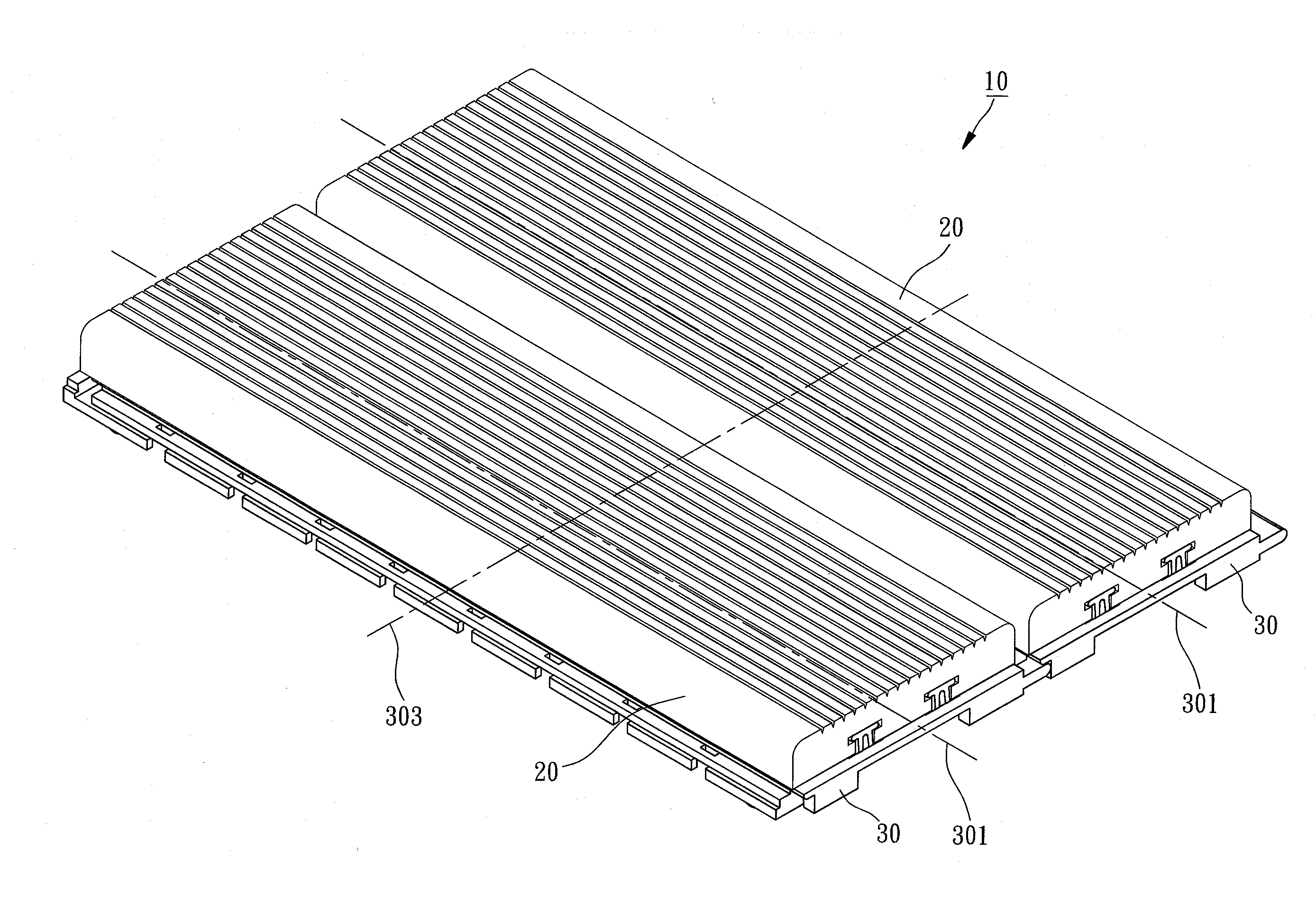
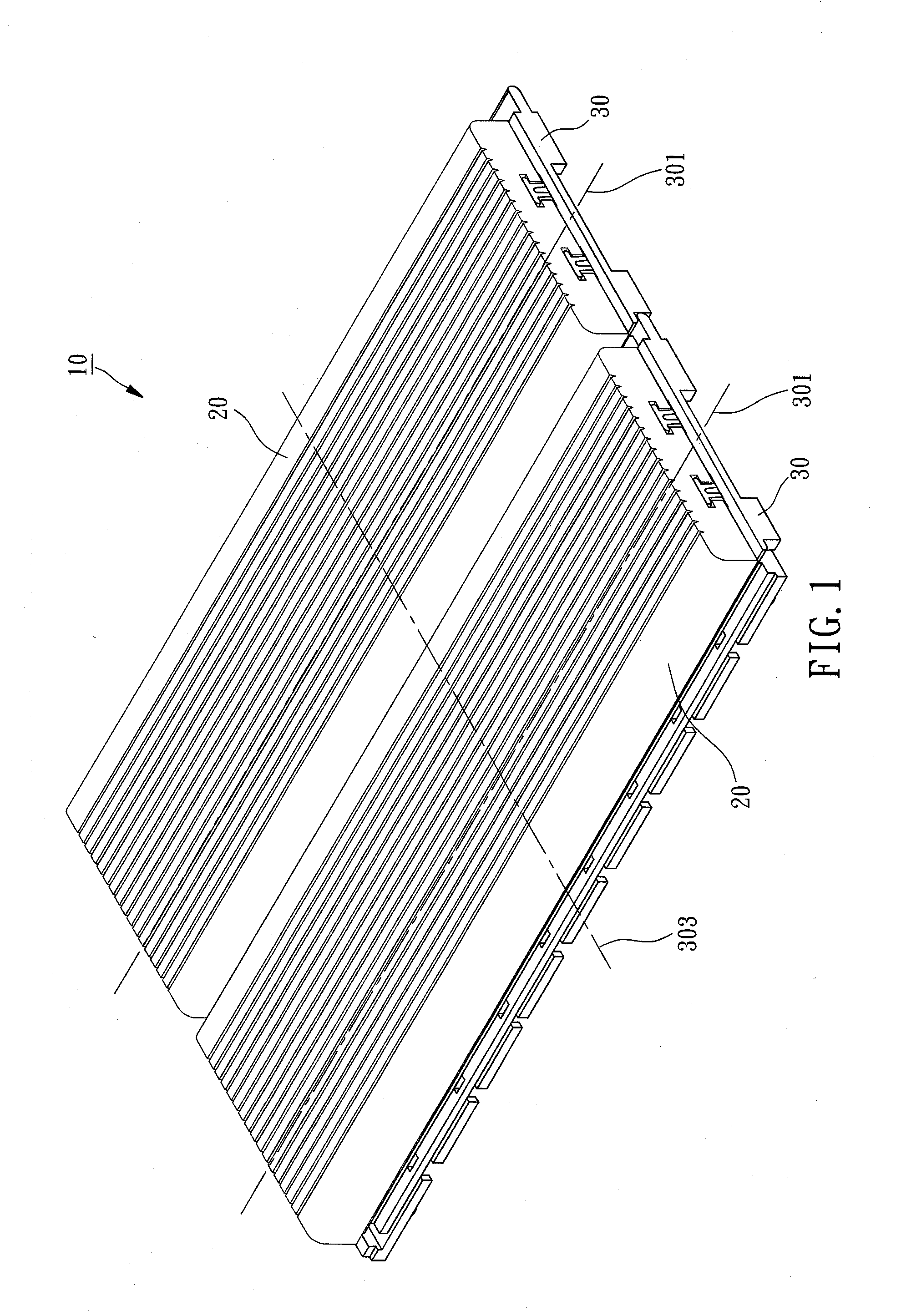
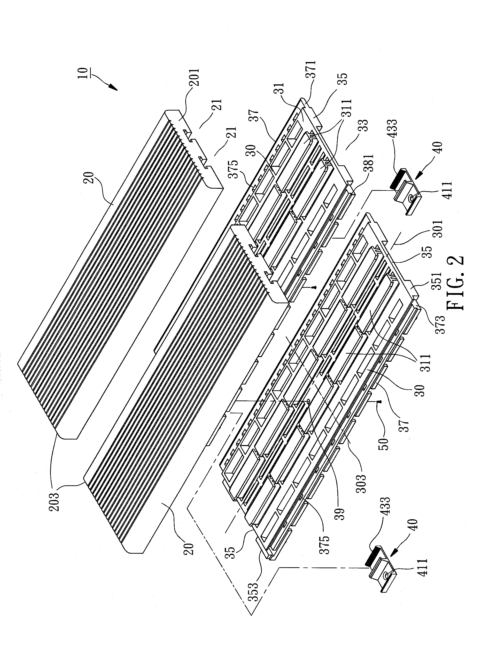
[0032]Referring to FIG. 1 and FIG. 2, an outdoor floor covering 10 in a first preferred embodiment of the present invention comprises a plurality of planks 20, a plurality of bases 30, and at least a fastening element 40.

[0033]In the first preferred embodiment, the planks 20 are made of wood and are solid or composite. A sliding groove 21 is disposed at the bottom of each plank 20.

[0034]In the first preferred embodiment, the bases 30 are each formed by plastic injection molding and made of PE, PP, PS, PVC, PMMA, ABS, PA, or POM. The bases 30 each have a top surface 31, a bottom surface 33, two opposing first sidewall surfaces 35, and two opposing second sidewall surfaces 37. The first sidewall surfaces 35 are connected in a direction defined as a horizontal long axial direction 301. The second sidewall surfaces 37 a...


PUM


Abstract

An outdoor floor covering includes a plurality of planks, a plurality of bases, and at least a fastening element. A positioning portion of each base is slidably disposed in a sliding groove of each plank. Adjacent ones of first sidewall surfaces of the bases are engaged with each other through engaging portions. Adjacent ones of second sidewall surfaces of the bases abut against each other through protruding and dent portions. At least a fastening element is engaged and connected between adjacent ones of the second sidewall surfaces of the bases. Hence, the outdoor floor covering of the present invention enables quick assembly and prevents the planks and bases from undergoing displacement horizontally or vertically. Accordingly, the outdoor floor covering is quick and convenient to lay, exhibits satisfactory structural stability, and enhances pedestrian safety.

Description

BACKGROUND OF THE INVENTION[0001]1. Technical Field[0002]The present invention relates to floor coverings, and more particularly, to an outdoor floor covering which is convenient to lay and exhibits satisfactory structural stability.[0003]2. Description of Related Art[0004]A conventional outdoor floor covering is laborious and time-consuming to lay, because the laying process requires mounting a plurality of keels on the ground to provide foundations, and fixing multiple planks to the keels with a nail gun to finalize the assembly. Furthermore, the planks deform as a result of high humidity and temperature changes, and thus the nails get loosened gradually and exposed from the planks eventually, thereby jeopardizing pedestrians walking on the planks Moreover, the underlying keels rot gradually when immersed in rainwater accumulated under the planks after downpours. As time passes, the overall structural stability of the outdoor floor covering deteriorates.[0005]Furthermore, recent y...

Claims


Application Information

Patent Timeline
Patent Type & Authority Applications(United States)
IPC IPC(8): E04F15/02E04B1/61
CPCE04F15/02044E04B1/54E04F15/02038E04F2203/06E04F2015/0205E04F2201/023E04F15/02183E04F15/02194
Inventor TSAI, YAO-HUNG
Owner NEXUS GLOBAL
Learn More