Photo-voltaic cell device and display panel
- Summary
- Abstract
- Description
- Claims
- Application Information
AI Technical Summary
Benefits of technology
Problems solved by technology
Method used
Image
Examples
first embodiment
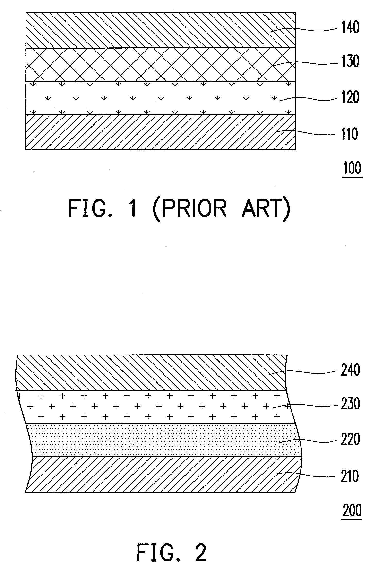
[0035]FIG. 2 is a schematic structural view of a photo-voltaic cell device according to a first embodiment of the present invention. Referring to FIG. 2, the photo-voltaic cell device 200 of the present embodiment includes a first electrode 210, an N-type doped silicon-rich dielectric layer 220, a P-type doped silicon-rich dielectric layer 230, and a second electrode 240. The N-type doped silicon-rich dielectric layer 220 is disposed on the first electrode 210, and the N-type doped silicon-rich dielectric layer 220 is doped with an N-type dopant. The P-type doped silicon-rich dielectric layer 230 is disposed on the N-type doped silicon-rich dielectric layer 220, and the P-type doped silicon-rich dielectric layer 230 is doped with a P-type dopant. The second electrode 240 is disposed on the P-type doped silicon-rich dielectric layer 230.
[0036]Said vertical design can also be changed to a horizontal design or a lateral design (not shown) in an modified embodiment of the present invent...
second embodiment
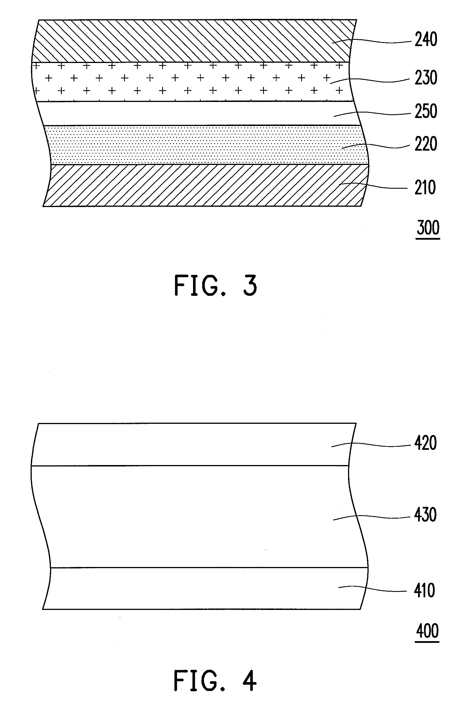
[0049]FIG. 4 is a schematic view of a display panel according to a second embodiment of the present invention. FIG. 5 is a schematic cross-sectional view of a first substrate depicted in FIG. 4. Referring to FIGS. 4 and 5, the display panel 400 of the present embodiment has a pixel region P1 and a sensing region P2. The display panel 400 includes a first substrate 410, a second substrate 420, and a display medium 430 including such as a liquid crystal material, an organic light emitting material, an electrophoretic material, or the like. A pixel array 412 and at least a photo-voltaic cell device 414 are disposed on the first substrate 410. The pixel array 412 is disposed in the pixel region P1 and includes a plurality of TFTs 412a and a plurality of pixel electrodes 412b electrically connected to the TFTs 412a. The photo-voltaic cell device 414 is disposed in the sensing region P2 and includes a first electrode 414a, a first silicon-rich dielectric layer 414b, a second silicon-rich ...
third embodiment
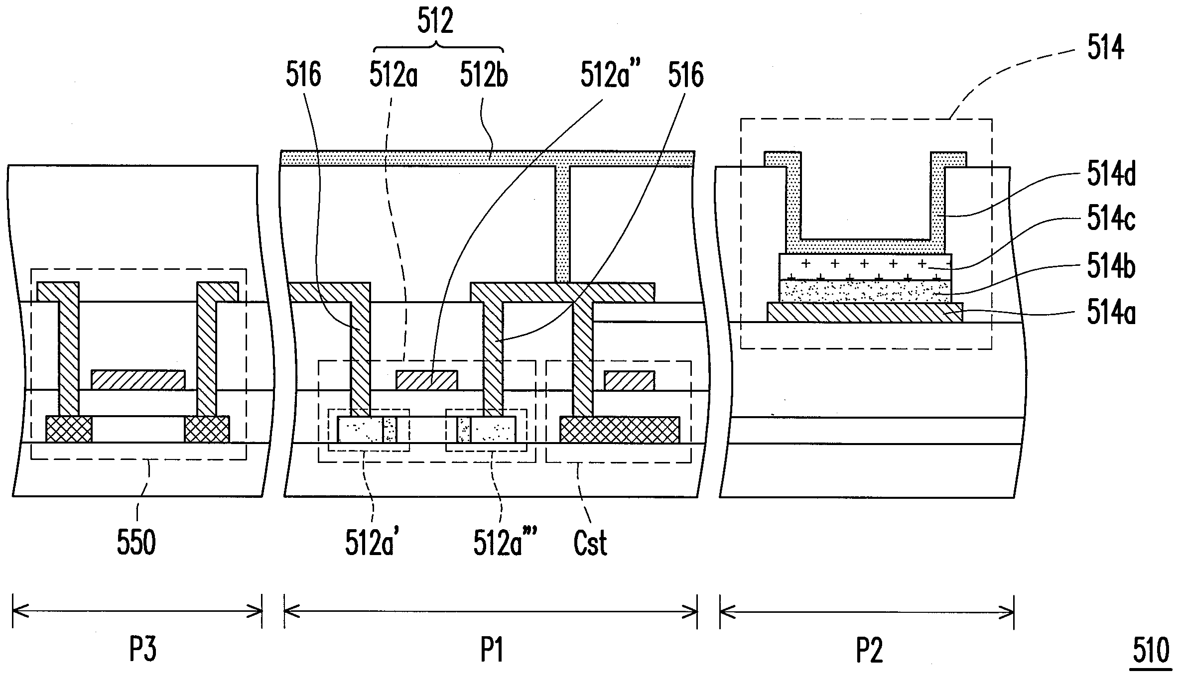
[0059]FIG. 6 is a schematic view of a display panel according to a third embodiment of the present invention. FIG. 7 is a schematic cross-sectional view of a first substrate depicted in FIG. 6. Referring to FIGS. 6 and 7, the display panel 500 of the present embodiment has a pixel region P1 and a sensing region P2. The display panel 500 includes a first substrate 510, a second substrate 520, and a display medium 530. A pixel array 512 and at least a photo-voltaic cell device 514 are disposed on the first substrate 510. The pixel array 512 is disposed in the pixel region P1 and includes a plurality of TFTs 512a and a plurality of pixel electrodes 512b electrically connected to the TFTs 512a. The photo-voltaic cell device 514 is disposed in the sensing region P2 and includes a first electrode 514a, a first silicon-rich dielectric layer 514b, a second silicon-rich dielectric layer 514c, and a second electrode 514d. The first silicon-rich dielectric layer 514b is disposed on the first e...
PUM
 Abstract
Description
Claims
Application Information
 - R&D
- Intellectual Property
- Life Sciences
- Materials
- Tech Scout
- Unparalleled Data Quality
- Higher Quality Content
- 60% Fewer Hallucinations
Browse by: Latest US Patents, China's latest patents, Technical Efficacy Thesaurus, Application Domain, Technology Topic, Popular Technical Reports.
© 2025 PatSnap. All rights reserved.Legal|Privacy policy|Modern Slavery Act Transparency Statement|Sitemap|About US| Contact US: help@patsnap.com


