Air filter system and air filter element for an air filter system

a filter element and air filter technology, applied in the field of air filter system, can solve the problem of excessive airflow reduction, and achieve the effect of reliable, convenient and easy filter element replacemen

Active Publication Date: 2015-03-05
MANN HUMMEL GMBH
View PDF5 Cites 3 Cited by
  • Summary
  • Abstract
  • Description
  • Claims
  • Application Information

AI Technical Summary

Benefits of technology

[0035]According to a further aspect, the invention relates to a filter element for installation in a filter system preferably with one or several features as described above and in the following, wherein the filter element is arranged in the housing of the filter system such that it can be replaced. Using such a filter element in the described filter system will ensure reliable sealing between the area of the unfiltered and the area of the filtered medium, which can be maintained during operation and particularly also can be reliably restored by means of a

Problems solved by technology

If the secondary element is also heavily contaminated, however, then it mus

Method used


Image

  • Air filter system and air filter element for an air filter system
  • Air filter system and air filter element for an air filter system
  • Air filter system and air filter element for an air filter system

Examples


Embodiment Construction

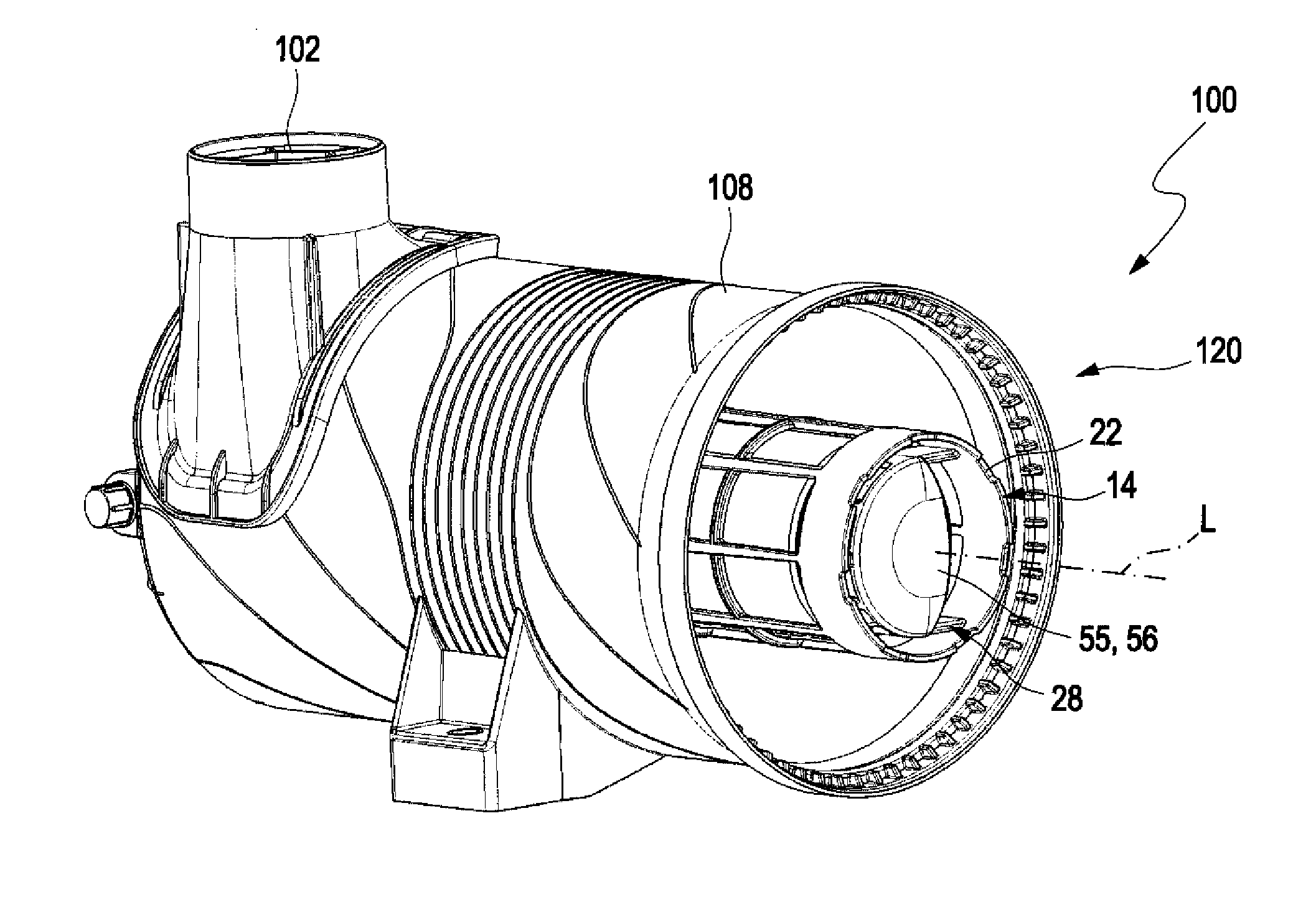
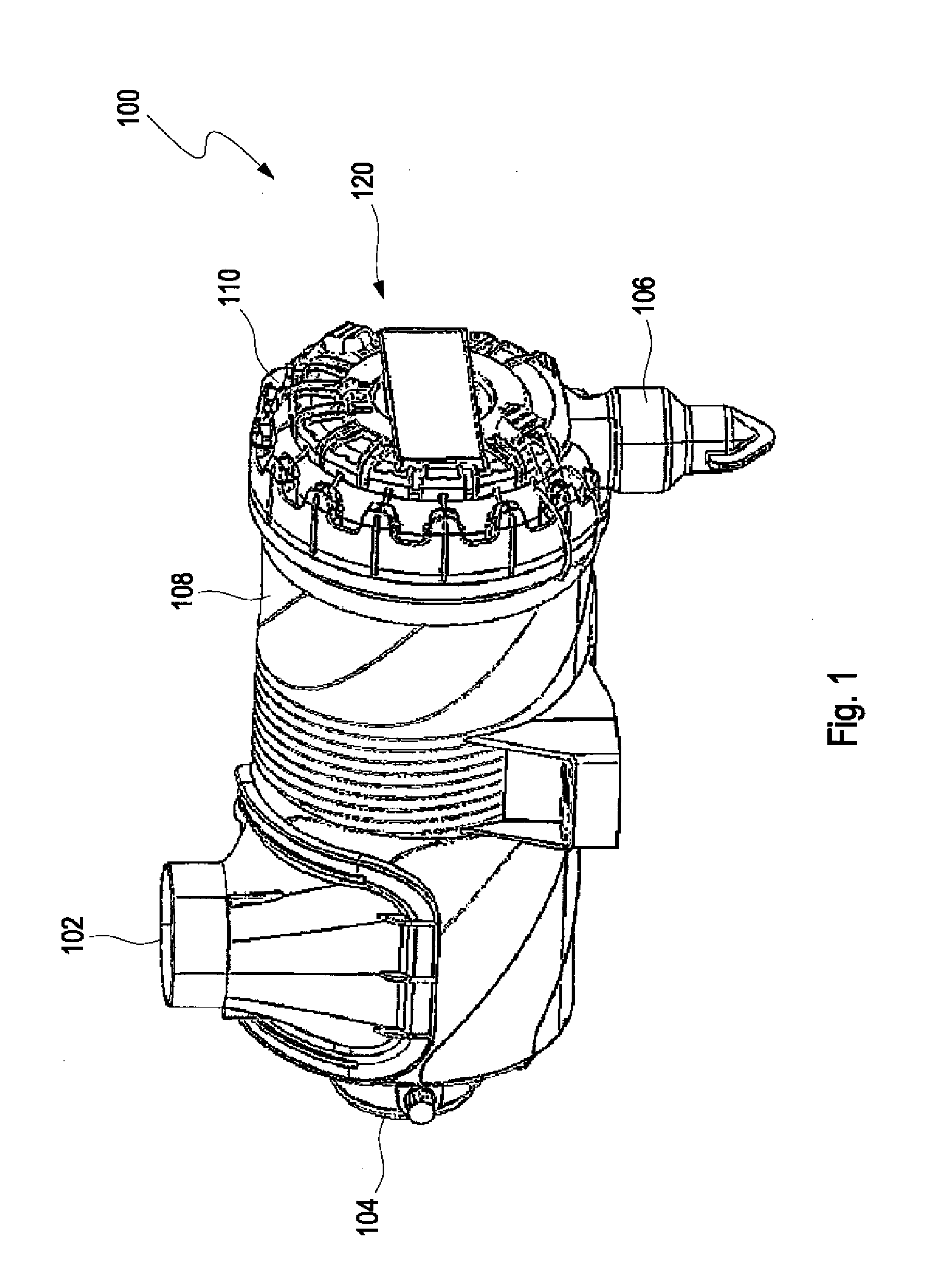
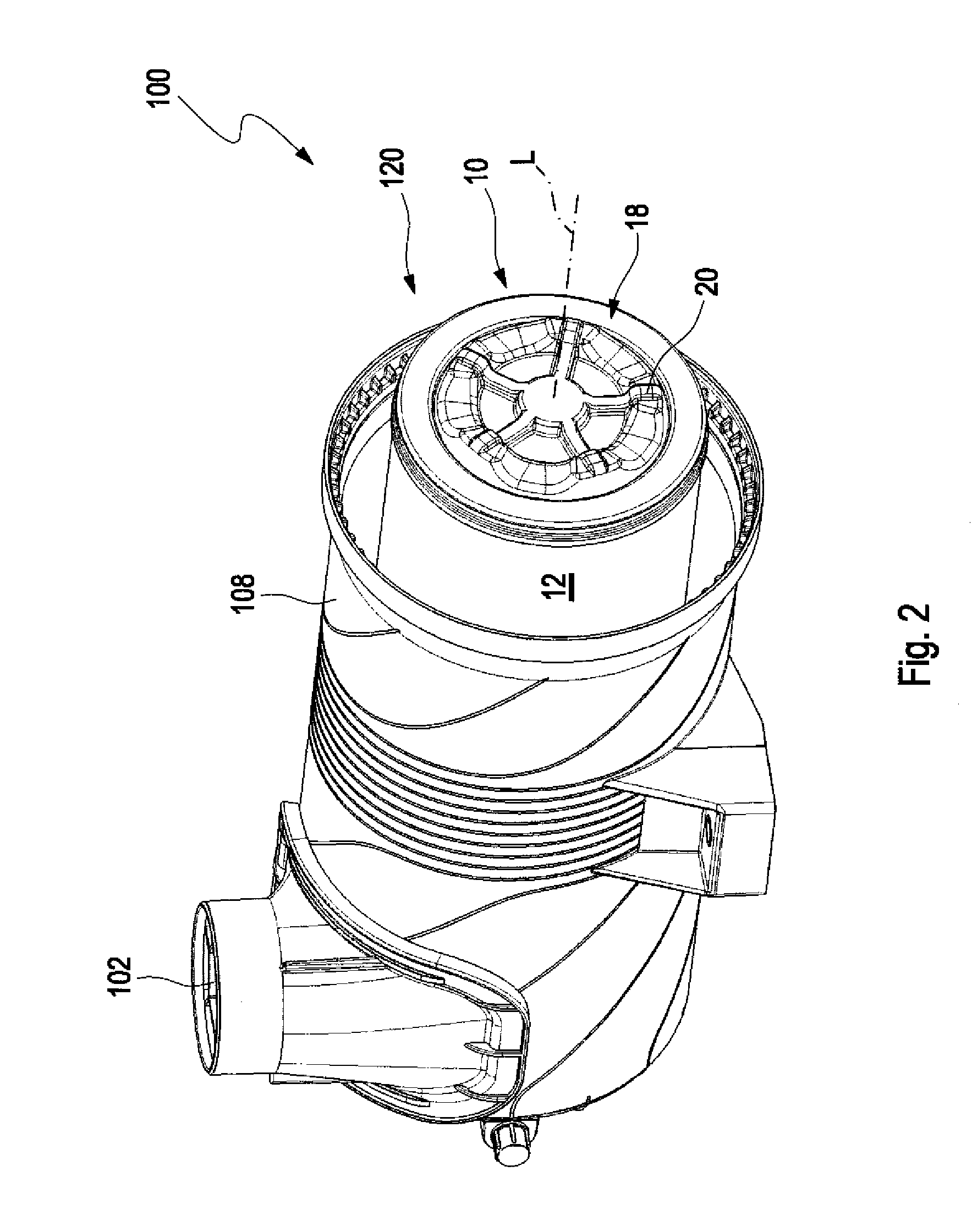
[0047]FIG. 1 illustrates a perspective view of a filter system 100 according to an embodiment of the invention, with a tangential inlet 102, a central outlet 104, and a dirt outlet 106 at the bottom. Shown is a circular filter design that comprises a housing 108, which is closed with a cover 110 on one front face 120. In the air filter system, air loaded with dust flows through the inlet 102, which is arranged tangentially to the housing wall and to the air filter element that is installed on the inside, also tangentially into the flow chamber receiving the untreated flow which surrounds the annular air filter element so that the air inside the housing 108 is put into a rotary motion. A direct ingress of the air through inlet 102 into the pleats of the air filter element present in the inlet area is prevented by a baffle plate on the filter element, which is formed, for example, by the one filter element in the inflow area which is designed as a film as part of the filter element an...


PUM

PropertyMeasurementUnit
Forceaaaaaaaaaa
Areaaaaaaaaaaa

Abstract

A filter system for intake air of an internal combustion engine has a housing with a cover. A filter element is arranged in the housing. An inlet feeds a medium to be filtered into the housing and an outlet discharges the medium from the housing. The filter element has a filter body with first end face and opposite second end face. The filter element has an open first end plate at the first end face and a second end plate at the second end face. A support tube is arranged concentrically about a longitudinal axis in the housing and attached with a first end to the housing. The support tube is arranged in the interior of the filter element and radially supports the filter body. The second end plate rests on the second end of the support tube and on an inner cover contour of the cover with anti-rotation action.

Description

CROSS-REFERENCE TO RELATED APPLICATIONS[0001]This application claims the benefit of German patent application Nos. 10 2013 014 488.4, filed Sep. 2, 2013; 10 2013 014 489.2, filed Sep. 2, 2013; 10 2013 014 507.4, filed Sep. 2, 2013; 10 2013 014 492.2, filed Sep. 2, 2013; 10 2013 014 491.4, filed Sep. 2, 2013; and 10 2013 014 493.0, filed Sep. 2, 2013. The entire contents of the aforesaid German patent applications being incorporated herein by reference and to the fullest extent of the law.[0002]This application claims the benefit of U.S. provisional patent application Nos. 62 / 038,312, filed: Aug. 17, 2014; 62 / 038,575, filed: Aug. 18, 2014; 62 / 038,601, filed: Aug. 18, 2014; 62 / 038,920, filed: Aug. 19, 2014; 62 / 038,672, filed: Aug. 18, 2014 and 62 / 038,869, filed Aug. 19, 2014. The entire contents of the aforesaid provisional patent applications being incorporated herein by reference and to the fullest extent of the law.BACKGROUND OF THE INVENTION[0003]The invention relates to an air fi...

Claims


Application Information

Patent Timeline
IPC IPC(8): F02M35/02F02M35/022F02M35/024
CPCF02M35/0203F02M35/0216F02M35/0223F02M35/02416B01D46/0046B01D46/521F02M35/02483Y10T29/49826B01D46/0002B01D46/0001F02M35/09B01D46/2411B01D46/2414B01D46/0027B01D46/522B01D46/0005B01D2265/06B01D46/60F02M35/024B01D46/0004B01D46/0086B01D2265/021B01D2279/60
Inventor RUHLAND, KLAUS-DIETERKAUFMANN, MICHAEL
Owner MANN HUMMEL GMBH
Why Eureka
Try Eureka