

Immobilization system
- Summary
- Abstract
- Description
- Claims
- Application Information
AI Technical Summary
Benefits of technology
Problems solved by technology
Method used
Image

Examples
Embodiment Construction
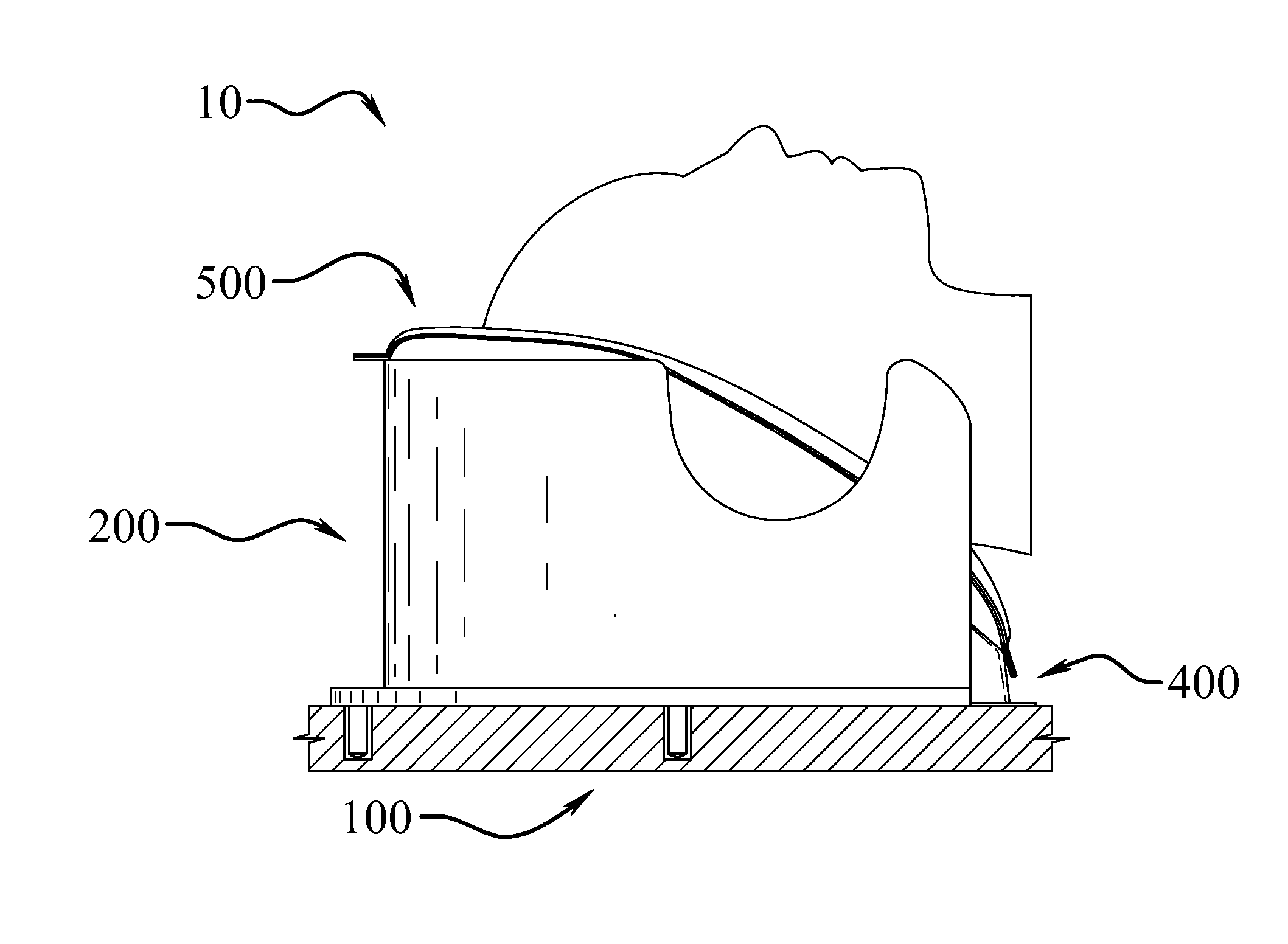
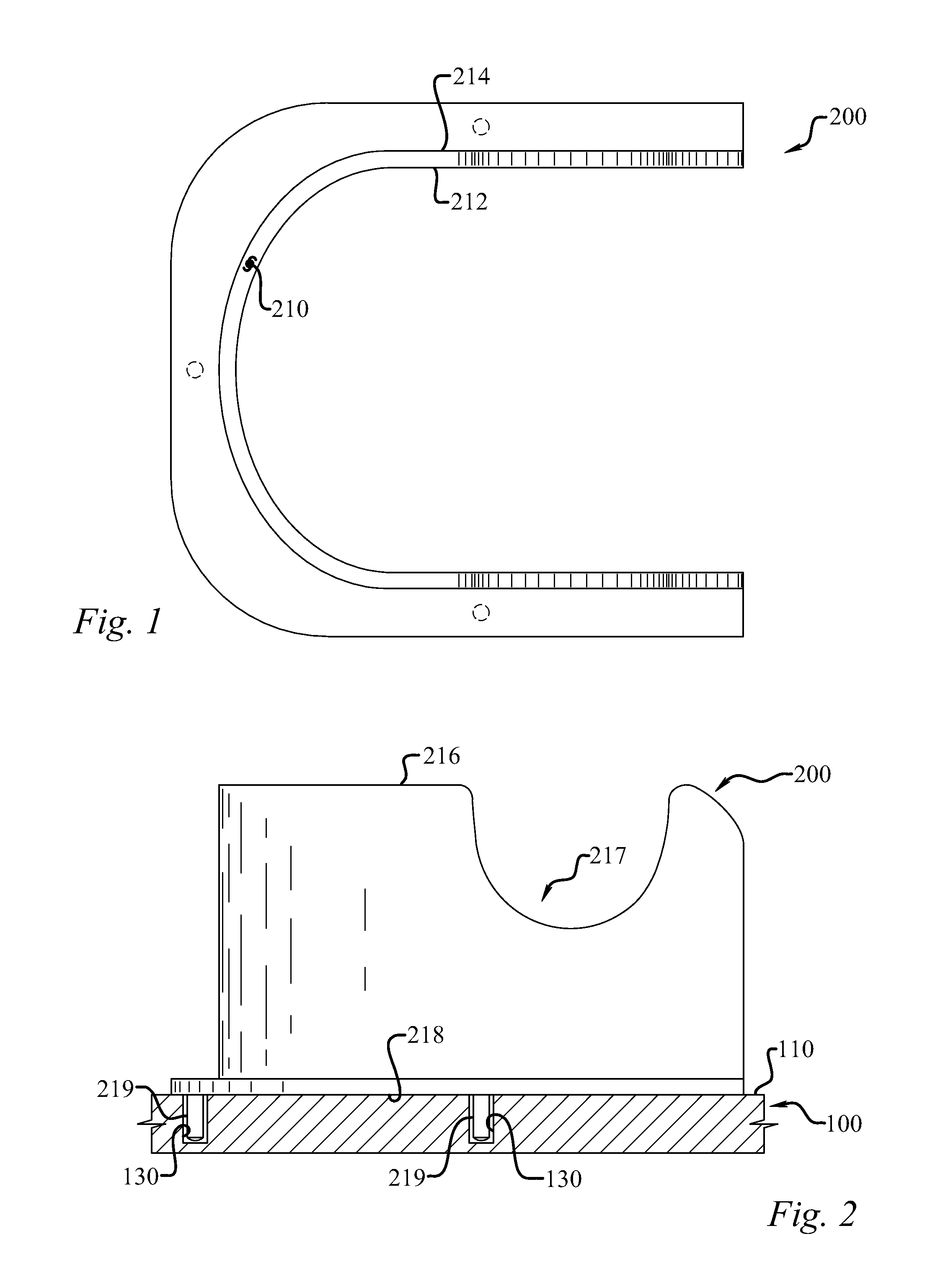
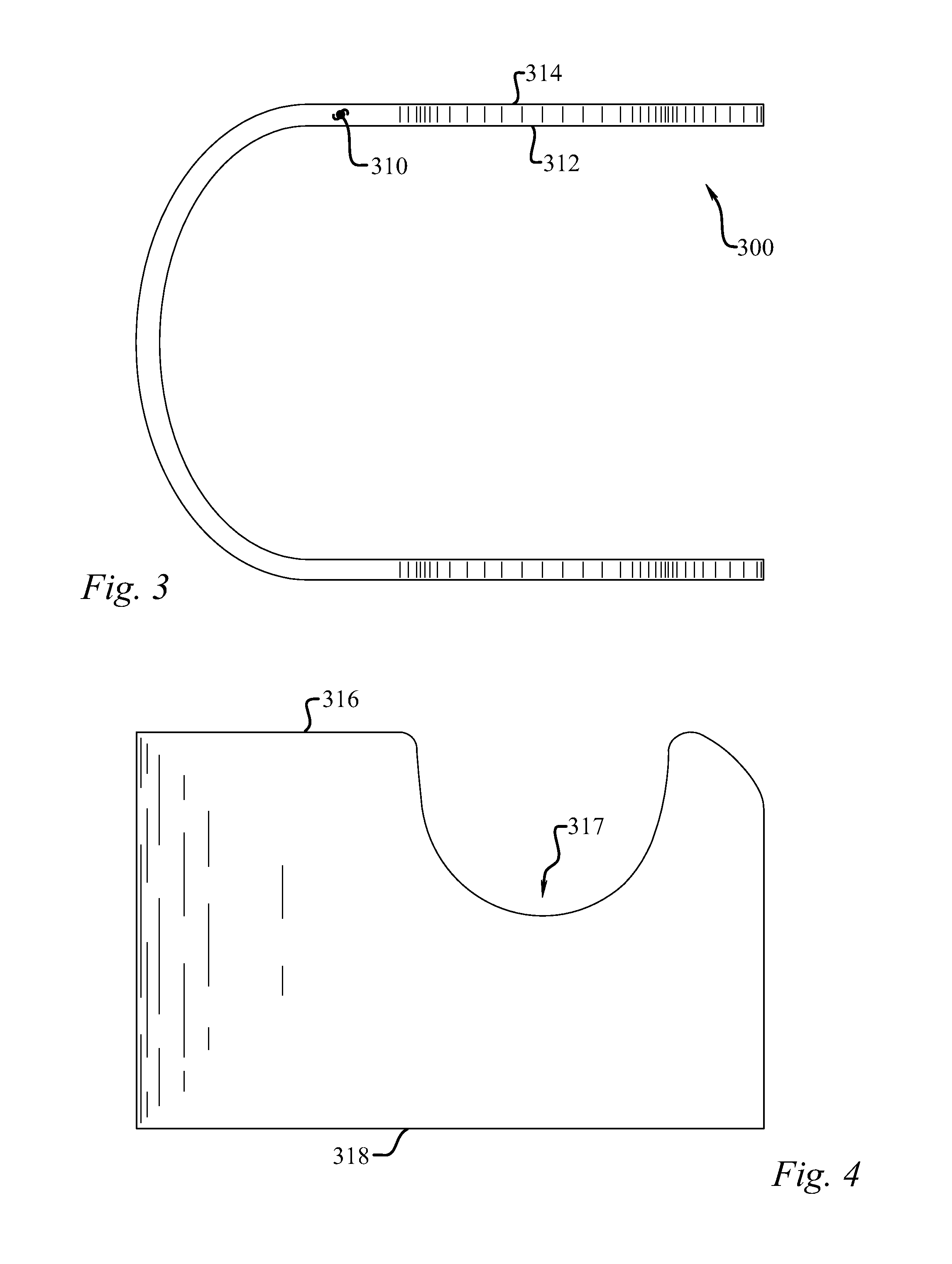
[0036]What is claimed then, as seen in FIGS. 1-13, is an immobilization system (10) for highly reproducible patient positioning. In one embodiment, the system (10) includes a fixation apparatus (100) with at least an upper surface (110), as seen well in FIG. 2. This may be a generally flat plate that is removable from other equipment, but may represent any surface to which the system is generally attached. The fixation apparatus (100) has various apparatus attachment fixtures (130), which may or not be placed on or as a part of the upper surface (100), that are reversibly attachable to a primary forming shell (200), seen well in conjunction with the fixation apparatus (100) in FIG. 1. The primary forming shell may have a primary forming shell sidewall (210), a primary forming shell sidewall interior surface (212), a primary forming shell sidewall exterior surface (214), a primary forming shell sidewall upper edge (216) and a primary forming shell sidewall engagement surface (218). T...
PUM
 Abstract
Description
Claims
Application Information