Plug reception assembly and method of reducing restriction in a borehole

Active Publication Date: 2015-03-05
BAKER HUGHES INC
View PDF6 Cites 43 Cited by
  • Summary
  • Abstract
  • Description
  • Claims
  • Application Information

AI Technical Summary

Benefits of technology

[0002]Disclosed herein is a method of reducing restriction in a borehole that is configured for a multizone fracturing operation, wherein the borehole has a plurality of plug reception assemblies and each of the plurality of plug receptio

Problems solved by technology

Though these devices work well for the purpose for which they were designed, the process for removing the restrictions they form, once they are no longer nee

Method used


Image

  • Plug reception assembly and method of reducing restriction in a borehole
  • Plug reception assembly and method of reducing restriction in a borehole

Examples


Embodiment Construction

[0006]A detailed description of one or more embodiments of the disclosed apparatus and method are presented herein by way of exemplification and not limitation with reference to the Figures.

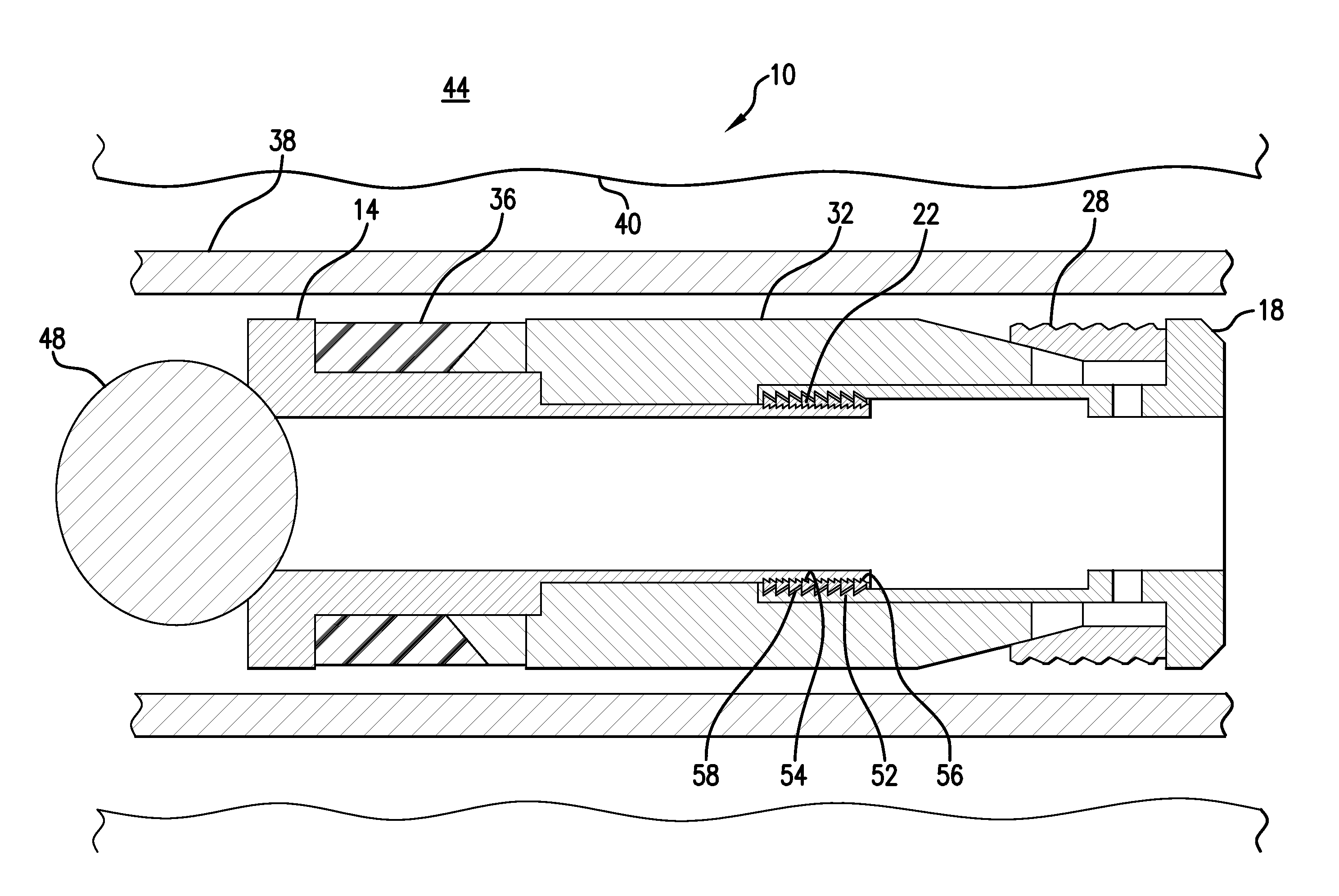
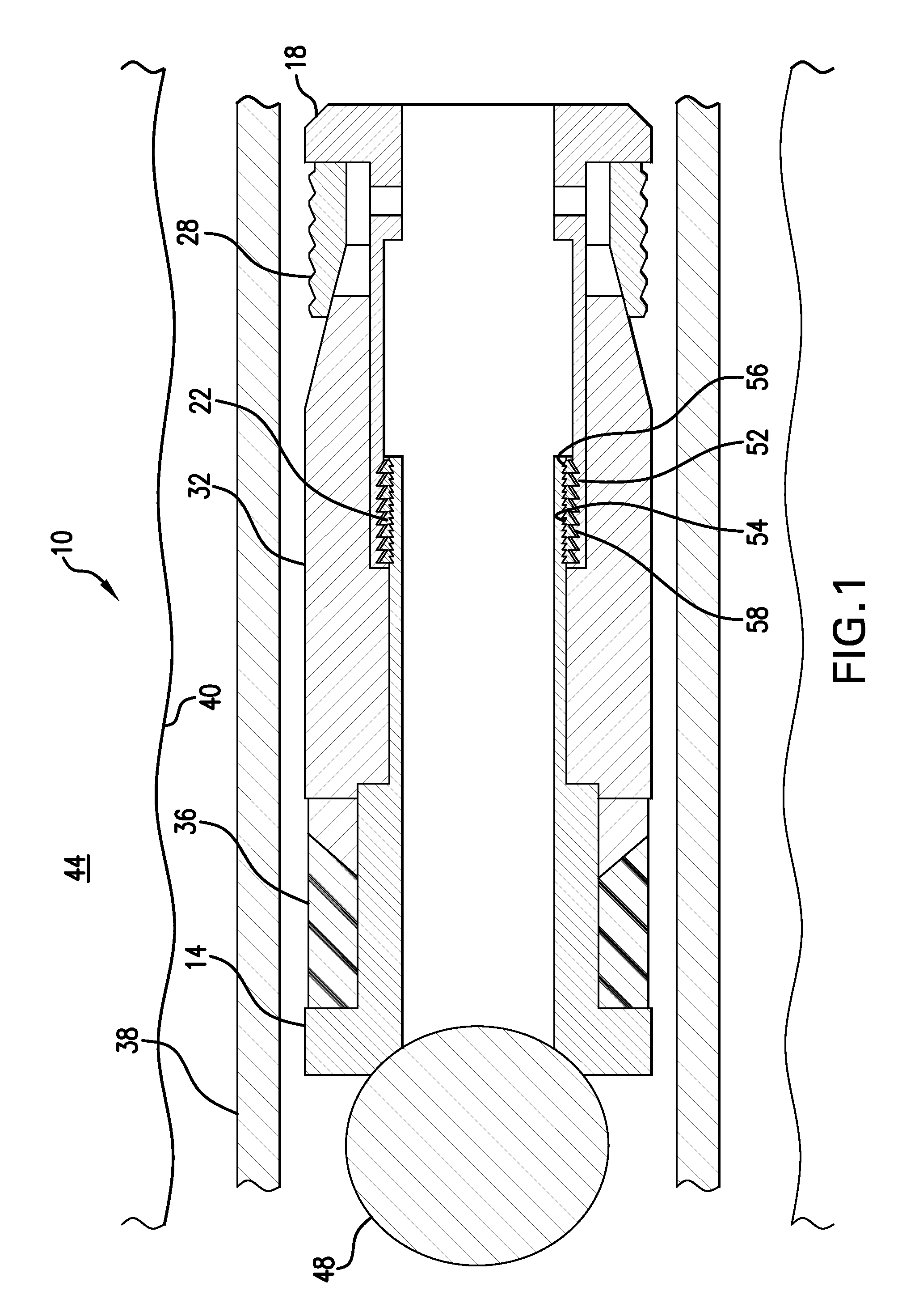
[0007]Referring to FIG. 1, a plug reception assembly disclosed herein is illustrated at 10. The plug reception assembly 10, shown herein as a frac plug, includes a plurality of components. In this embodiment the components include a mandrel 14, a housing 18, a body lock ring 22, at least one slip 28, a cone 32, and an elastic member 36, illustrated herein as a seal. One or more of the components 14, 18, 22, 28, 32 and 36 and subsets thereof are assemblable together to form the plug reception assembly 10.

[0008]The plug reception assembly 10 is positionally fixable within a liner or casing 38, or other tubular, or open borehole 40 in an earth formation 44 and is seatingly receptive to a plug 48 run thereagainst. The plug reception assembly 10, when plugged with one of the plugs 48 can allow pressur...


PUM


Abstract

A method of reducing restriction in a borehole that is configured for a multizone fracturing operation wherein the borehole has a plurality of plug reception assemblies and each of the plurality of plug reception assemblies includes at least one component configured to disintegrate upon exposure to a selected condition. The method includes exposing the at least one component to a disintegrating environment and facilitating restriction reduction.

Description

BACKGROUND[0001]Devices have been available for some time for seatingly receiving a plug within a tubular such as in the downhole hydrocarbon and carbon sequestration industries. These devices necessarily form a restriction within the tubular and typically have features that maintain the devices at fixed positions within the tubular. Though these devices work well for the purpose for which they were designed, the process for removing the restrictions they form, once they are no longer needed, can be costly in both time and money. Removal of such devices from the respective tubular positions can in some cases require running a shifting tool or a cutting tool to the device before it can be disengaged from the tubular. In some cases, this might require an additional dedicated run in the hole with attendant delays and monetary costs. Those who practice in the art will therefore be receptive to devices and methods that overcome the foregoing drawbacks.BRIEF DESCRIPTION[0002]Disclosed her...

Claims


Application Information

Patent Timeline
IPC IPC(8): E21B29/02E21B33/12
CPCE21B33/12E21B29/02
Inventor XU, YINGQING
Owner BAKER HUGHES INC
Why Eureka
Try Eureka