Vehicle body frame structure for automobile

a technology for automobiles and body frames, applied in the direction of superstructure connections, steering links, transportation and packaging, etc., can solve the problems of displaced downward movement of the suspension components of the mounted suspension, and achieve the effects of increasing the crash stroke of the vehicle, simple structure, and increasing the weight of the vehicl

Active Publication Date: 2015-03-05
HONDA MOTOR CO LTD
View PDF19 Cites 28 Cited by
  • Summary
  • Abstract
  • Description
  • Claims
  • Application Information

AI Technical Summary

Benefits of technology

[0048]According to the above-described aspect (1) of the invention, if the collision load in the vehicle body longitudinal direction is input, the sub-frame is bent down at the central bending point, and the adjacent side fastening portion is extracted downward from the cabin side support member together with one end portion side of the link stay. The rear portion of the sub-frame is rotated about the support bolt on the under-floor frame together with the link stay. Therefore, it is possible to reliably guide the sub-frame and the suspension component downward below the cabin.
[0049]Therefore, according to this aspect of the invention, when the collision load in the vehicle body longitudinal direction is input, it is possible to reliably guide the sub-frame and the suspension component downward below the cabin by using a simple structure. Accordingly, it is possible to obtain an increased crash stroke of the vehicle without resulting in increased vehicle weight or increased manufacturing cost.
[0050]Furthermore, according to this aspect of the invention, the nut is held by the lateral wall on the side separating from the floor tunnel portion of the link stay, and the support bolt is fitted into the nut from the lower side of the floor tunnel portion. Accordingly, when the vehicle body is assembled, it is possible to facilitate the fitting work of the support bolt into the nut in a wide space below the floor tunnel portion. Therefore, there is an advantage in that workability is improved.
[0051]According to the above-described aspect (2) of the invention, the nut is integrally attached to the nut cover having the engagement claw. Therefore, the nut cover is locked in advance at a predetermined position on the lateral wall of the link stay. In this manner, even when the space in the peripheral region on the side where the nut is arranged is narrow, the support bolt can be fitted into the nut in a state where the nut is accurately positioned.
[0052]According to the above-described aspect (3) of the invention, the restricting projection which is locked by the bolt insertion portion and restricts the rotation of the nut is disposed at the nut. Therefore, a worker can fit the support bolt into the nut without holding the nut portion.
[0053]According to the above-described aspect (4) of the invention, the displacement permitting portion is disposed at the bolt insertion portion on the lateral wall of the link stay. Therefore, when the adjacent side fastening portion of the sub-frame is displaced in the under-floor frame direction, the displacement permitting portion can permit the displacement of the link stay. Therefore, according to this aspect of the invention, before the link stay functions as a link, it is possible to prevent the link stay from being unnecessarily deformed.

Problems solved by technology

When this vehicle body frame structure is employed, if the rotary lever arm loosens the nut by using the thrust force of the explosive in the case of vehicle front collision, the rear end portion of the sub-frame falls down together with the bolt, thereby causing the mounted suspension component to be displaced downward.

Method used


Image

  • Vehicle body frame structure for automobile
  • Vehicle body frame structure for automobile
  • Vehicle body frame structure for automobile

Examples


first embodiment

[0116]Hereinafter, a first embodiment of this invention will be described with reference to the drawings. Unless otherwise particularly designated, terms of “front”, “rear”, “up”, “down”, “left” and “right” in the following description mean terms of “front”, “rear”, “up”, “down”, “left” and “right” in a vehicle.

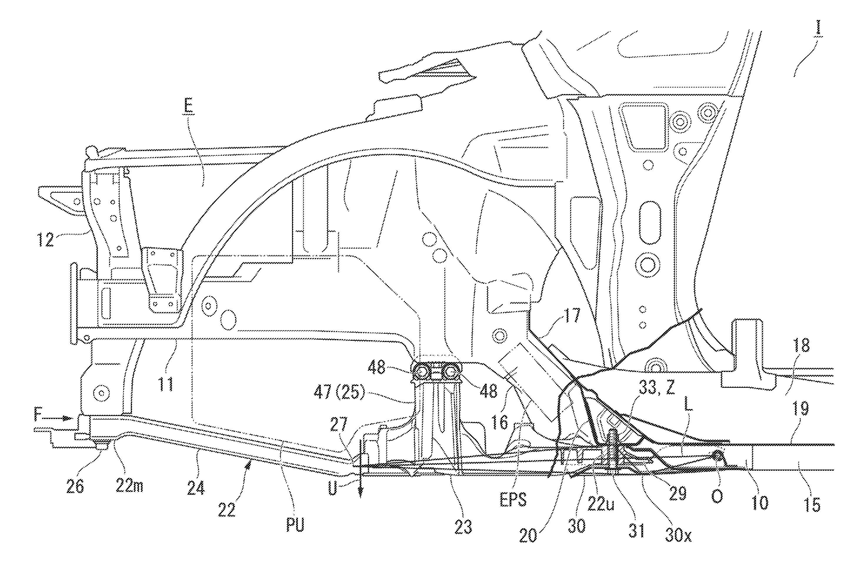
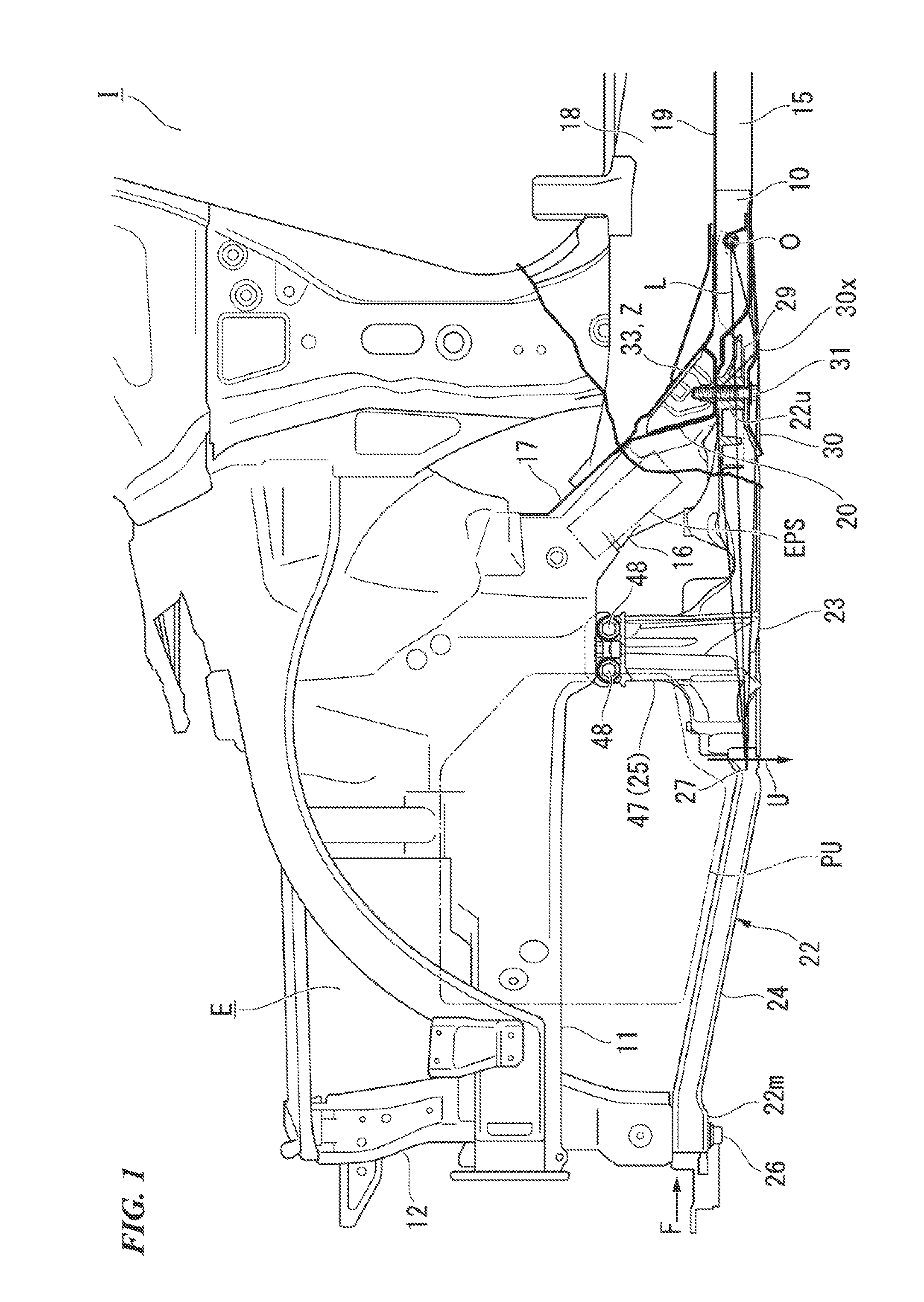
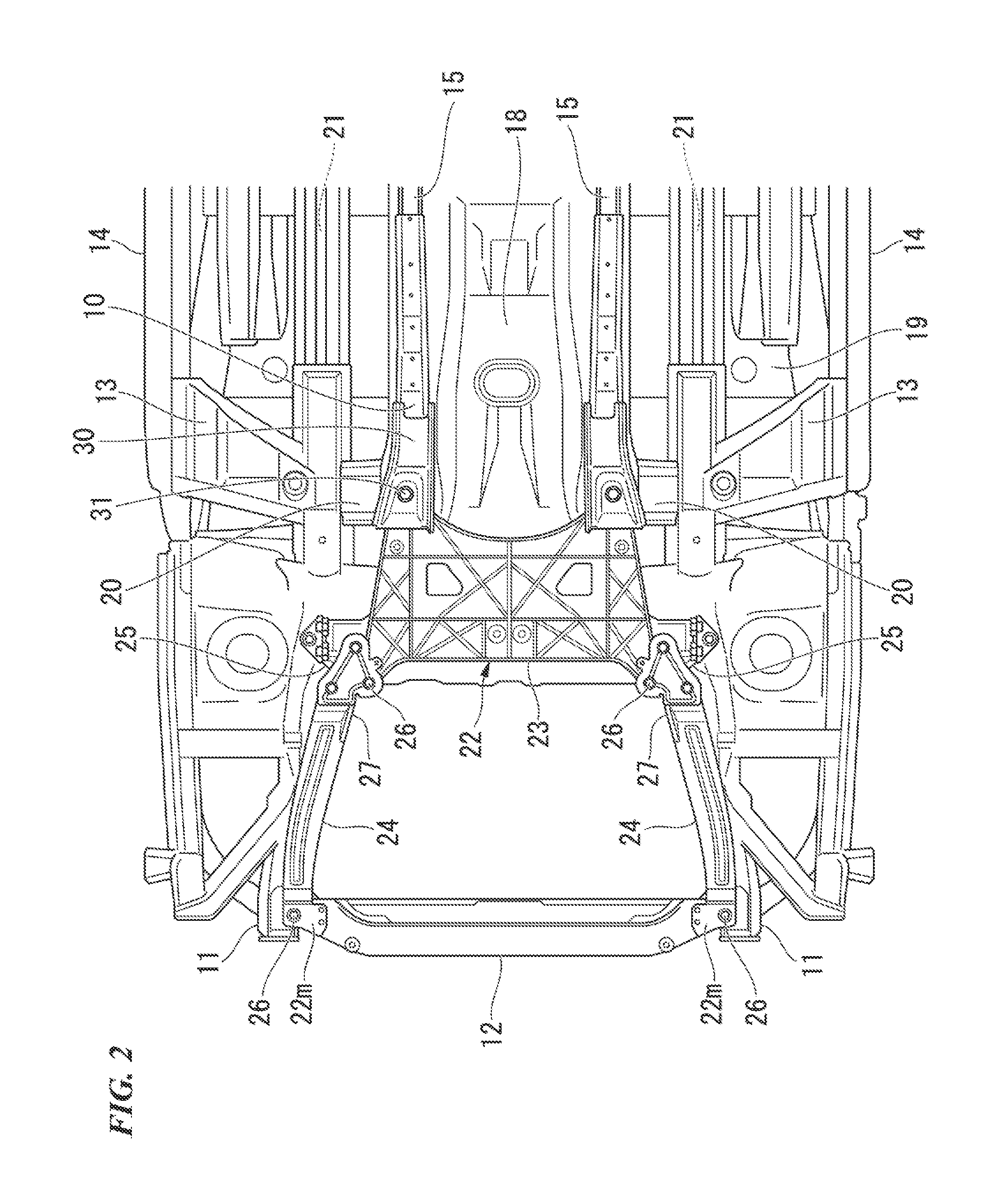
[0117]FIG. 1 is a view showing a left side surface on a front part side of a vehicle according to this embodiment in a partially cut away cross-sectional view. FIG. 2 is a view when a front part region of the vehicle is viewed from below. FIG. 3 is a view when a front part lower side of the vehicle is viewed obliquely from above.

[0118]As shown in FIGS. 1 to 3, a rear end portion of a dash lower panel 17 which separates a cabin I and an engine compartment E in front thereof is joined to a front end portion of a floor panel 19 facing the inside of the cabin I. The dash lower panel 17 is erected obliquely upward from a joint portion with the floor panel 19. In addition, in a cen...

second embodiment

[0193]Next, a vehicle body frame structure for an automobile according to a second embodiment of this invention will be described with reference to the drawings, using a vehicle body front part structure as an example.

[0194]As shown in FIGS. 1 to 3, the rear end portion of the dash lower panel 17 is joined to the front end portion of the floor panel 19, and the front side of the dash lower panel 17 is formed so as to rise obliquely upward. The floor tunnel portion 18 is attached to the central portion in the vehicle width direction of the floor panel 19 along the vehicle body longitudinal direction, over a portion leading to the rear end portion of the dash lower panel 17. In both side portions of the floor tunnel portion 18, the floor panel 19 is configured so that the height is lowered outward in the vehicle width direction by two steps. In FIGS. 2 and 3, the dash lower panel 17 is omitted in the illustration.

[0195]A pair of right and left front side frames 11 and 11 (side frames)...

third embodiment

[0245]Next, a third embodiment will be described. The same reference numerals are given to the configuring elements which are the same as those in the above-described embodiments, and a description thereof will be simplified or omitted here.

[0246]In this embodiment, the fastening bolt 31 (fastener or bolt) and the weld nut 33 (head portion, fastener, nut) configure the first fastening member.

[0247]As shown in FIG. 38, the front end extension member 10 (front end extension portion, under-floor frame, other vehicle body panel) is fastened and fixed to the lateral wall 30s of the rear end portion (second end portion side) of the link stay 30 by the support bolt 39 (second fastening member). The support bolt 39 is inserted into the bolt holding portion 42 of the support bracket 43 through the through-hole 50 on the lateral wall 40 of the front end extension member 10, and the nut 38 (second fastening member) is screwed to the distal end portion of the support bolt 39 which penetrates bo...


PUM


Abstract

A vehicle body frame structure includes a side frame, a sub-frame, a cabin side support member, an under-floor frame, and a link stay. The sub-frame includes a separate side fastening portion, an adjacent side fastening portion, and a central bending point. In the link stay, a first end portion side is fastened to a lower surface of the cabin side support member together with the adjacent side fastening portion so as to be extractable, and a second end portion side is fastened to the under-floor frame. A nut for fastening the second end portion side of the link stay is held by a lateral wall on a side separating from the floor tunnel portion of the link stay, and the support bolt is fitted into the nut from a lower side of a floor tunnel portion in a vehicle width direction serving as an axis.

Description

TECHNICAL FIELD[0001]This invention relates a vehicle body frame structure on a front side or on a rear side of a cabin in a four-wheeled vehicle. In addition, this invention relates to a vehicle body frame structure for an automobile.[0002]Priority is claimed on Japanese Patent Application No. 2012-114580 filed May 18, 2012, Japanese Patent Application No. 2012-125160 filed May 31, 2012, Japanese Patent Application No. 2012-125161 filed May 31, 2012, and Japanese Patent Application No. 2012-200850 filed Sep. 12, 2012, the content of which is incorporated herein by reference.BACKGROUND ART[0003]A technology is known in which in a case of vehicle front collision, a certain vehicle among automobiles ensures a crash stroke of a vehicle body front part by bending down a lower member located behind a front cross member, and by causing a suspension component such as a stabilizer supported by the lower member to be displaced downward (refer to Patent Document 1).[0004]In addition, as a tec...

Claims


Application Information

Patent Timeline
Patent Type & Authority Applications(United States)
IPC IPC(8): B62D21/15B62D27/06B62D21/11
CPCB62D21/155B62D27/065B62D21/11B62D24/00B62D25/082
Inventor WATANABE, YASUNORIARIMA, TETSUHIROOKADA, HIDEYUKIFUNAKOSHI, AKIHITO
Owner HONDA MOTOR CO LTD
Why Eureka
Try Eureka