Energy conversion device using change of contact area and contact angle of liquid
Active Publication Date: 2015-03-05
KOREA ELECTRONICS TECH INST +1
0 Cites 4 Cited by
AI-Extracted Technical Summary
Problems solved by technology
However, a method and a device of prior art for converting energy using a fluid have various problems for commercialization.
First, since a reversible movement, wherein a drop-like liquid metal, which has been moved inside the narrow and thin channel, is returning back to its original position when the external force is removed, is difficult, there is a limitation in that a separate lubricating layer is required and an inoperable condition happens due to the easy occurrence of the channel blocking phenomenon.
Moreover, since a method and a device of prior art for converting energy using a fluid adopt a narrow and thin channel structure, the two facing electrodes must be patterned with a fixed shape on the channel wall, and the device config...
Benefits of technology
[0040]The present invention varies the gap between a pair of electrodes by using an external physical force, and utilizes the resulting changes in the contact angle and the contact area of the liquid in electrical energy generation; thus, it has an effect of implementing an energy conversion device having less failures with a simplified device structure and a reduced manufacturing cost by preventing the channel blocking pheno...
Abstract
The present invention relates to a method and a device for converting energy using a change of a contact area and a contact angle of liquid and, more specifically, to a method and a device for converting mechanical energy into electric energy by applying a reciprocal phenomenon of electrowetting, wherein liquid and gas are positioned between two facing substrates and energy is converted by using a volume change of a fluid, such that the present invention has the advantages of preventing channel-blocking without requiring all facing electrodes to be patterned, simplifying a device configuration, implementing easy control, and removing the need to apply an external power source.
Application Domain
Influence generatorsKinetic-electric generator
Technology Topic
Electric energyEngineering +6
Image
Examples
- Experimental program(1)
Example
[0047]The advantages and the features of the present invention, and the method for achieving thereof will become apparent with reference to the exemplary embodiments described in detail hereinafter with the accompanying drawings. However, the present invention will not be limited to the exemplary embodiments described hereinafter, but will be implemented in a various different forms, and the exemplary embodiments are provided for the completeness of the disclosure of the present invention and to teach an ordinary person of skill in the art of the scope of the invention completely, and the present invention is only be defined by the scope of the claims. Meanwhile, the terms used in the description, is for describing the exemplary embodiments, but not to limit the present invention.
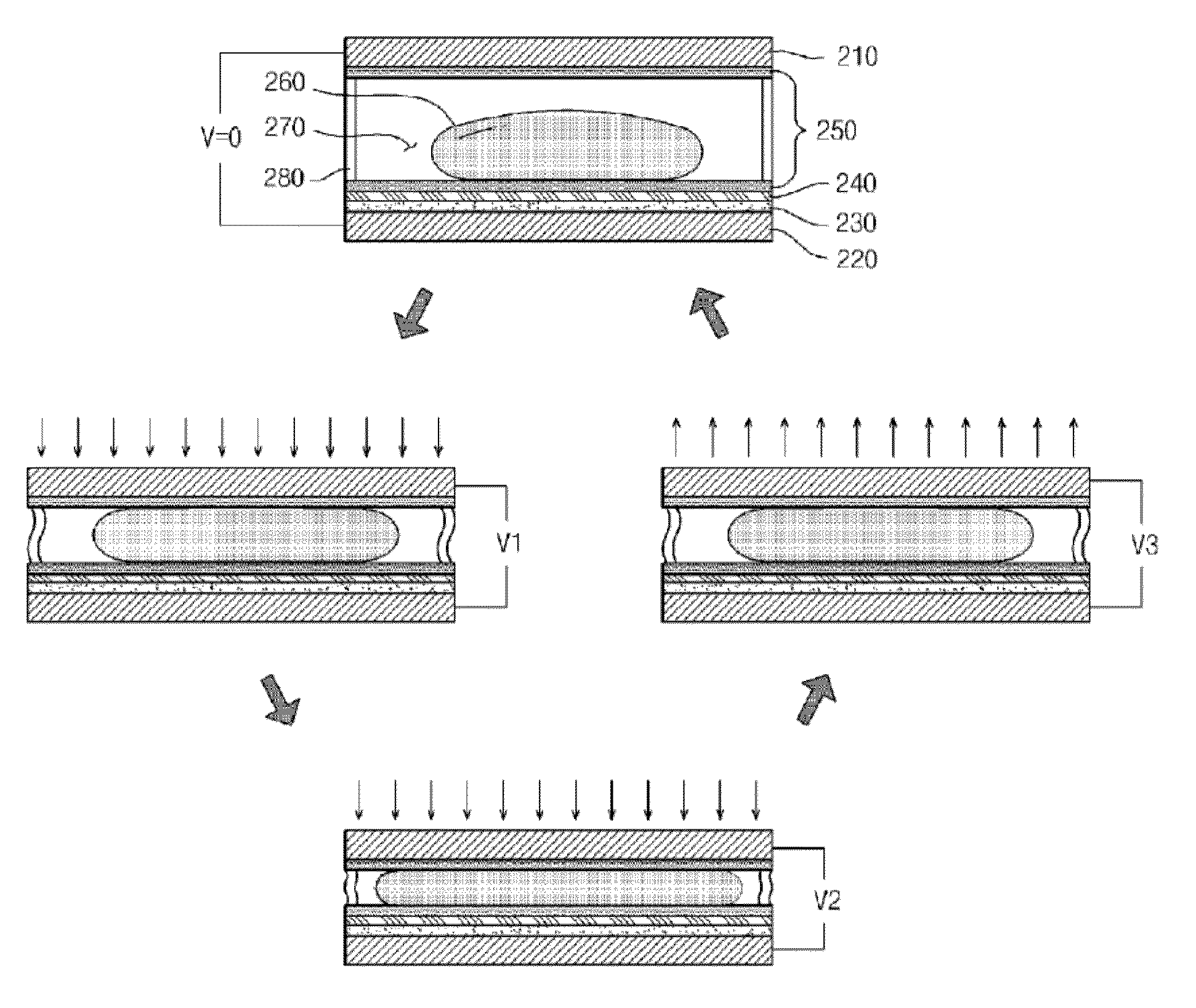
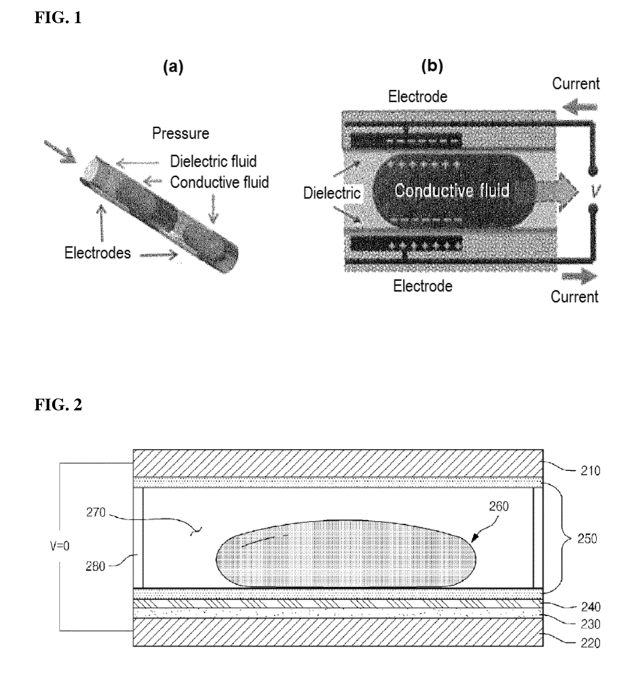
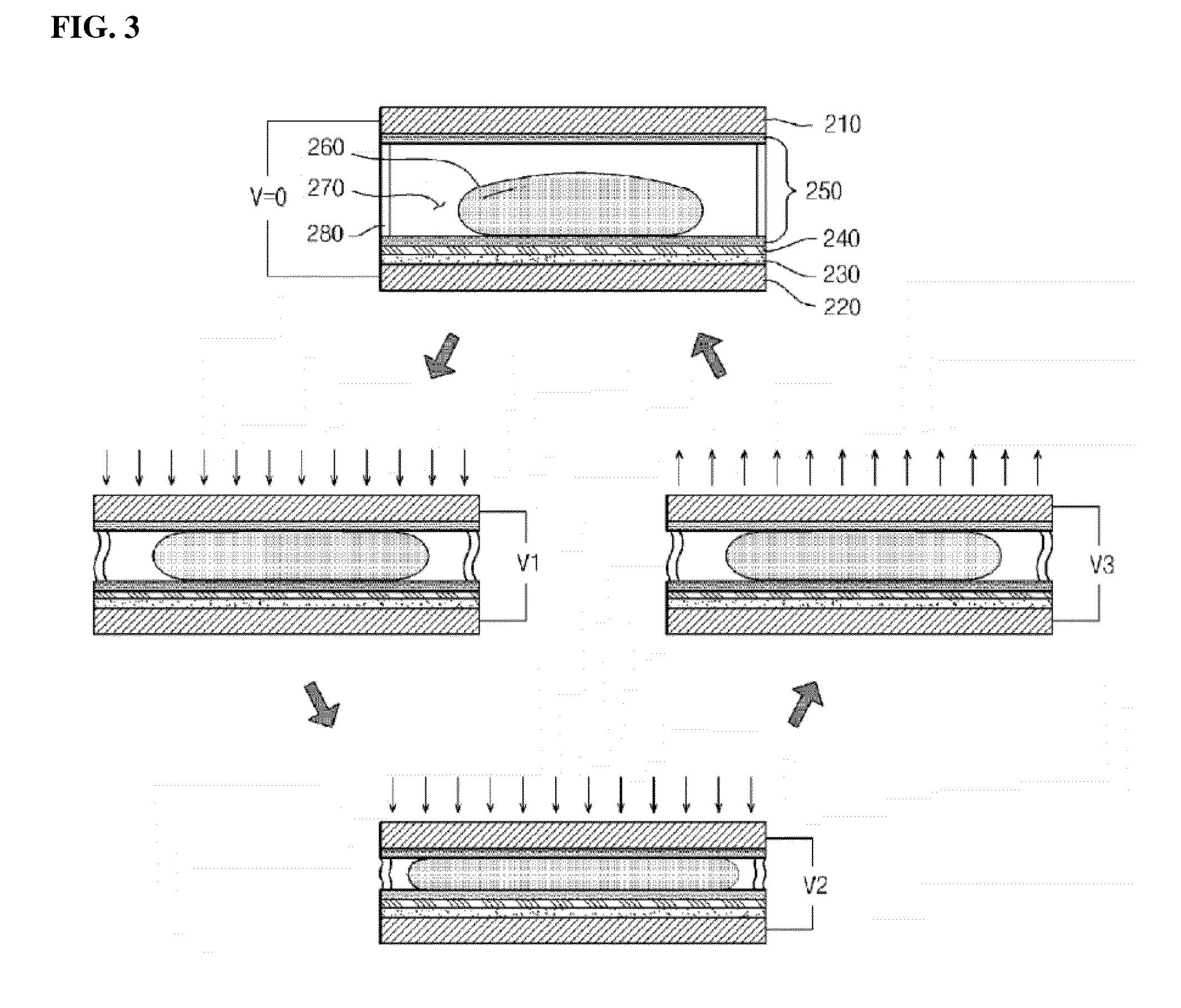
[0048]FIG. 2 is a block diagram of a device for converting energy using a fluid according to an exemplary embodiment of the present invention. According to FIG. 2, a device for converting energy using a fluid according to an exemplary embodiment of the present invention includes a lower electrode substrate 220 and an upper electrode substrate 210 facing each other, wherein an electrode is disposed on said electrode substrate, and an ionic liquid or a water 260 is located in between the pair of electrodes.
[0049]Preferably, a non-conductive gas 270 is filled in the space between the lower electrode substrate 220 and the upper electrode substrate 210.
[0050]In such a device for converting energy using the contact angle and the contact area of a liquid according to an exemplary embodiment of the present invention, the distance between the upper electrode substrate and the lower electrode substrate, i.e. the gap, is changing when an external physical force is applied, and by the reacting force thereof, the contact area and the contact angle of the ionic liquid and the water, which are being contact with the upper electrode substrate 210 or the lower electrode substrate 220, are changing. When the contact area of the ionic liquid or water 260 is changing, the capacitance of the electrode is changing, thereby generating electrical energy.
[0051]FIG. 3 is a drawing showing the energy generation process by a device for converting energy using a fluid according to an exemplary embodiment of the present invention. As illustrated in FIG. 3, initially, the generated electrical energy output of the device for converting energy using a fluid according to an exemplary embodiment of the present invention is 0. Later, by applying an external physical force to the upper electrode substrate 210, electrical energy V1, V2 having a consistent polarity are generated as the contact area between the ionic liquid or water 260 and the upper electrode substrate 210 or the lower electrode substrate 220 varies. At this time, when the external physical force is removed or reduced, the ionic liquid or water is restored to the original shape as the gap between the upper electrode substrate and the lower electrode substrate becomes wider, thus, again the contact area between the ionic liquid or water varies, thereby generating another electrical energy V3 having an opposite polarity than the case when an external physical force is applied thereto.
[0052]Again according to FIG. 2, a device for converting energy using a fluid according to an exemplary embodiment of the present invention further includes a partition 280 which supports a gap between the lower electrode substrate 220 and the upper electrode substrate 210.
[0053]The partition 280, as illustrated in FIG. 3, has restoring force or flexibility, wherein shape change occurs by an external physical force, and restores its original shape when the external physical force is removed
[0054]According to a preferred exemplary embodiment of the present invention, the lower electrode substrate 220 or the upper electrode substrate 210 may also be configured to have restoring force or flexibility.
[0055]Preferably, although the partition 280 is a rigid form, the contact with the lower electrode substrate 220 or the upper electrode substrate 210 is flexible so the partition 280 may be freely pushed away, or the upper electrode substrate 210 may be flexible while the partition 280 and the lower electrode substrate 220 are rigid, or both may be flexible. It can be configured if the structure is capable of generating change in the contact area where the upper electrode substrate 210 and the ionic liquid or water 260 are in contact, by an external physical force.
[0056]According to a preferred exemplary embodiment of the present invention, the height of the partition 280, or the gap between the upper electrode substrate and the lower electrode substrate is determined by the size of the diameter of the ionic liquid or water 260, and preferably it would be no more than two times of the diameter of the ionic liquid or water 260. Besides, during the operation of energy conversion, the gap between the upper electrode substrate 210 and the lower electrode substrate 220 must be smaller than the diameter of the ionic liquid or water 260.
[0057]In addition, according to another preferred exemplary embodiment of the present invention, the partition 280 has at least any one shape of a rectangle, a triangle, an inverted triangle, a circle, an ellipse, or a cylinder.
[0058]Thus, an energy conversion device according to an exemplary embodiment of the present invention can be connected in array form by the partition 280. In other words, said energy conversion device may have a triangular shape, a rectangular shape, a pentagonal shape, a hexagonal shape, a circular shape, a grid shape, or a honeycomb shape by the partition 280.
[0059]In addition, preferably, the shape of the partition 280 may be
[0060]a rectangle, a triangle, an inverted triangle, a circle, an ellipse, or a cylinder, and the shape of a unit cell (comprising an upper plate, a lower plate, a partition, a liquid, and a gas) of the energy conversion device could possibly be a triangular shape, a rectangular shape, a pentagonal shape, a hexagonal shape, a circular shape, a grid shape, or a honeycomb shape.
[0061]According to a preferred exemplary embodiment of the present invention, an energy conversion device according to an exemplary embodiment of the present invention includes an energy conversion layer formed by stacking an inorganic material layer 230 and an organic material layer 240 on the lower electrode substrate 220 and/or the upper electrode substrate 210. Method such as patterning, vacuum deposition, or spin coating may be used in forming an energy conversion layer.
[0062]In stacking the inorganic material layer 230 and the organic material layer 240 on the lower electrode substrate 220 or on the upper electrode substrate 210, the order of stacking will not matter, however, they must be stacked adjacently.
[0063]Preferably, the inorganic material layer 230 and the organic material layer 240 may be alternately and repeatedly filed up when being stacked on the lower electrode substrate 220 or on the upper electrode substrate 210. In other words, an energy conversion layer can be formed by repeatedly stacking the inorganic material layer 230 and the organic material layer 240.
[0064]According to a preferred exemplary embodiment of the present invention, a hydrophobic material layer 250 is further stacked on the energy conversion layer comprising the inorganic material layer 230 and the organic material layer 240 so that the shape of said ionic liquid or water 260 is restored to its original shape when the external physical force is removed.
[0065]Preferably, the hydrophobic material layer 250 may be stacked on
[0066]the upper electrode substrate 210 and the lower electrode substrate 220 wherein the energy conversion layer is not yet formed.
[0067]According to a preferred exemplary embodiment of the present invention, the organic material layer 240 includes at least any one material or the combination of polymethylmethacrylate(PMMA), polyethylene(PE), polystyrene(PS), polyvinylpyrrolidone(PVP), poly(4-vinylpenol; PVP) or polyethersulfone(PES), poly(4-methoxyphenylacrylate; PMPA), poly(phenylacrylate; PPA), poly(2,2,2-trifluoroethyl methacrylate; PTFMA), cyanoethylpullulan(CYEPL), polyvinyl chloride(PVC), poly(parabanic acid resin; PPA), poly(t-butylstyrene; PTBS), polythienylenevinylene(PTV), polyvinylacetate(PVA), poly(vinyl alcohol; PVA), poly(rmethylstyrene; PAMS), poly(vinyl alcohol)-co-poly(vinyl acetate)-co-poly(itaconic acid)(PVAIA), polyolefin, polyacrylate, parylene-C, polyimide, octadecyltrichlorosilane(OTS), poly(triarylamine; PTTA), poly-3-hexylthiophene(P3HT), cross-linked poly-4-vinylphenol (cross-linked PVP), poly(perfluoroalkenylvinyl ether), nylon-6, n-octadecylphosphonic acid(ODPA), and said inorganic material layer includes at least any one material of SiO2, TiO2, Al2O3, Ta2O5, tantalum pentoxide, zinc oxide(ZnO), tantalum pentoxide(Ta2O5), yttrium oxide(Y2O3), cerium oxide(CeO2), titanium dioxide(TiO2), barium titanate(BaTiO3), barium zirconate titanate(BZT), zirconium dioxide(ZrO2), lanthanum oxide(La2O3), hafnon(HfSiO4), lanthanum aluminate(LaAlO3), silicon nitride(Si3N4), as perovskite materials, strontium titanate(SrTiO3), barium strontium titanate(BST), lead zirconate titanate(PZT), calcium copper titanate(CCTO), or HfO2.
[0068]Preferably, a material having dielectric constant (K) lower than 4, may be used for the organic material 240; and a material having dielectric constant (K) higher than 5 may be used for the inorganic material 230.
[0069]According to another preferred exemplary embodiment of the present invention, in the lower electrode substrate 220 or the upper electrode substrate 210 of an energy conversion device using a fluid according to an exemplary embodiment of the present invention, a hydrophobic material layer 250 is stacked on the energy conversion layer comprising the inorganic material layer 230 and the organic material layer 240 so that the shape of said ionic liquid or water 260 is restored to its original shape when the external physical force is removed.
[0070]The hydrophobic material layer 250 comprises at least any one or a mixture of silane family material, fluoropolymer material, trichlorosilane, trimethoxysilane, pentafluorophenylpropyltrichlorosilane, (benzyloxy)alkyltrimethoxysilane(BSM-22), (benzyloxy)alkyltrichlorosilane(BTS), hexamethyldisilazane(HMDS), octadecyltrichlorosilane(OTS), octadecyltrimethoxysilane(OTMS), and divinyltetramethyldisiloxane-bis(benzocyclobutene)(BCB).
[0071]According to a preferred exemplary embodiment of the present invention,
[0072]the electrode used in the lower electrode substrate 220 or the upper electrode substrate 210 is an is an inorganic electrode including at least any one of ITO, IGO, chrome, aluminum, indium zinc oxide(IZO), indium gallium zinc oxide(IGZO), ZnO, ZnO2 or TiO2; or a metal electrode including at least any one of aluminum, iron or copper; or an organic electrode including at least any one of polyethylenedioxythiophene(PEDOT), carbon nano tube(CNT), graphene, polyacetylene, polythiophene(PT), polypyrrole, polyparaphenylene(PPV), polyanilinep), poly sulfur nitride or polyparaphenylenevinylene.
[0073]According to a preferred exemplary embodiment of the present invention,
[0074]the lower electrode substrate 220 or the upper electrode substrate 210 is a metal electrode, a glass electrode, or a polymer material substrate. Here, the polymer material substrate is a plastic substrate or a film including at least any one of polyethylene terephthalate(PET), polyarylate(PAR), polymethylmethacrylate(PMMA), polyethylenenaphthalate(PEN), polyethersulfone(PES), polyimide(PI), polycarbonate(PC) or fiber reinforced plastics(FRP).
[0075]According to a preferred exemplary embodiment of the present invention, a water may be used, and the ionic liquid 260 includes at least any one of NaCl, LiCl, NaNo3, Na2SiO3, AlCl3—NaCl, LiCl—KCl, H2O, KCL, Na, NaOH H2SO4, CH3COOH, HF, CuSO4, ethylene glycol, propylene glycol or AgCl.
[0076]According to a preferred exemplary embodiment of the present invention, the non-conductive gas 270 includes at least any one of air, oxygen, nitrogen, argon, helium, neon, krypton, xenon, or radon.
[0077]For an energy conversion device using a fluid according to another exemplary embodiment of the present invention, the above described said energy conversion devices using a fluid are being formed into a multiply connected arrangement, wherein the electrodes which are included in the lower electrode substrate 220 or the upper electrode substrate 210 are separately provided or used by more than two of the energy conversion devices.
[0078]FIG. 4 is a conceptual diagram illustrating another device for converting energy using the contact angle and the contact area of a liquid according to the present invention. According to FIG. 4, a device for converting energy using a fluid according to another exemplary embodiment of the present invention includes a lower electrode substrate 420 and an upper electrode substrate 410 facing each other, wherein electrodes are disposed on both the electrode substrate and a conductive liquid 460 is located in between the pair of electrodes. A non-conductive gas 470 is filled in the space between the lower electrode substrate 420 and the upper electrode substrate 410. In addition, an energy conversion layer for generating electrical energy is formed on the lower electrode substrate 420 or the upper electrode substrate 410 according to the changes in the contact angle and the contact area between the conductive liquid 460 and at least any one of the lower electrode substrate 420 and the upper electrode substrate 410.
[0079]Preferably, the upper electrode substrate 410 or the lower electrode substrate 420 includes an electrode, and such electrodes are insulated from the conductive liquid 460.
[0080]In such a device for converting energy using the contact angle and the contact area of a liquid according to an exemplary embodiment of the present invention, the distance between the upper electrode substrate 410 and the lower electrode substrate 420, i.e. the gap, is changing when an external physical force is applied, and by the reacting force thereof, the contact area and the contact angle of the conductive liquid 460, which are being contact with the upper electrode substrate 410 or the lower electrode substrate 420, are changing. When the contact area of the conductive liquid 460 is changing, the capacitance of the electrode is changing, thereby generating electrical energy.
[0081]According to a preferred exemplary embodiment of the present invention, it is advantageous in that said conductive liquid 460 may use mercury, lithium, gallium, kalium, NaK, bismuth, tin, natrium, natrium-kalium alloy, and the like; the range of the specific resistivity is 1 μΩ/§− to 1000μΩ/§−, and the dielectric constant K is under 5.
[0082]According to a preferred exemplary embodiment of the present invention, the energy conversion layer may be formed on both of the upper electrode substrate 410 and the lower electrode substrate 420, and may be configured to be a laminated form of an inorganic material layer 430 and an organic material layer 440, and patterning, vacuum deposition, and the like may be used as a stacking method.
[0083]According to another preferred exemplary embodiment of the present invention, on the energy conversion layer formed by stacking an inorganic material layer 430 and an organic material layer 440, a hydrophile material layer 450 is further stacked so that the shape of said conductive liquid 460 can be restored to the original shape when the external physical force is removed.
[0084]Preferably, the hydrophile material layer 450 may be stacked on the upper electrode substrate 410 and the lower electrode substrate 420 wherein the energy conversion layer is not yet formed.
[0085]According to a preferred exemplary embodiment of the present invention, the hydrophile material layer 450 includes at least any one material of poly acrylic acid(PAA), acrylamides, maleic anhydride copolymers, methacrylate, ethacrylate, amine-functional polymers, amine-functional polymers, polystyrenesulfonate(PSS), vinyl acids, vinyl alcohols, or functional group of —NH, —CO—, amino group —NH2, hydroxyl group —OH or carboxyl group —COOH.
[0086]Besides, in the present invention using a conductive liquid, the detailed descriptions of the technical contents related to features, structures, and the like of the materials for the electrode or the substrate constituting the upper electrode substrate 410 or the lower electrode substrate 420, the inorganic material layer 430, the organic material layer 440, the non-conductive gas 470, and the partition 480 are omitted since it can be configured according to the foregoing exemplary embodiments using a ionic liquid or the contents described in FIG. 2 or FIG. 3.
[0087]As reviewed before, when compared with prior art using more than two different kinds of liquids, the present invention may prevent blocking and mixing phenomena inside the channel, and also it does not require any lubricating layer.
[0088]Furthermore, although the technologies of prior art suggests an insulation layer comprising a single self assembly molecular monolayer and a single dielectric layer, or more layers of non-conductive layers, or the various combination thereof, however, the present invention suggests a structure for optimizing the energy conversion efficiency.
[0089]In other words, when using an ionic liquid, (according to the stacking order) a structure of electrode/inorganic material layer/organic material layer/hydrophobic material layer, or a structure of electrode/organic material layer/inorganic material layer/hydrophobic material layer is configured on at least one side of the substrate of the upper electrode substrate or the lower electrode substrate; while when using a conductive liquid, (according to the stacking order) a structure of electrode/inorganic material layer/organic material layer/hydrophile material layer, or a structure of electrode/organic material layer/inorganic material layer/hydrophile material layer is configured on both of the substrate of the upper electrode substrate and the lower electrode substrate
[0090]And, application of an external power source for depolarization is required in using a conductive liquid according to the technology of prior art, however, application of an external power source is not required in the present invention since the energy conversion layer performs depolarizing function for the ionic liquid
[0091]Although the preferred exemplary embodiments and the application examples are illustrated and described, heretofore, the present invention is not limited by the above described specific exemplary embodiments and the application examples, naturally, various variant embodiments are possible by a person of ordinary skill in the art without departing the gist of the present invention claimed within the scope of the claims, and these variant embodiments should not be individually understood from the technical spirit or the expectation of the present invention.
Description of Symbols 210: upper electrode substrate, 220: lower electrode substrate 230: inorganic material layer 240: organic material layer 250: hydrofphile material layer 260: ionic liquid or water 270: non-conductive gas, 280: partition
PUM


Description & Claims & Application Information
We can also present the details of the Description, Claims and Application information to help users get a comprehensive understanding of the technical details of the patent, such as background art, summary of invention, brief description of drawings, description of embodiments, and other original content. On the other hand, users can also determine the specific scope of protection of the technology through the list of claims; as well as understand the changes in the life cycle of the technology with the presentation of the patent timeline. Login to view more.
Similar technology patents
High Frequency Module for Filling Level Measurements in the W-Band
Owner:VEGA GRIESHABER GMBH & CO
Mounting film for liquid crystal display drive chip and method for manufacturing the same
Owner:INFOVISION OPTOELECTRONICS HLDG LTD
Through-silicon via interconnection formed with a cap layer
Owner:TAIWAN SEMICON MFG CO LTD
Occlusal screw, dental implant system and set
PendingUS20220087786A1good acceptanceless failure
Owner:Z SYST SCHWEIZ
Thin Film Transistor Substrate and Method of Manufacturing the Same
Owner:SAMSUNG ELECTRONICS CO LTD
Circuit substrate and light emitting diode package
Owner:EVERLIGHT ELECTRONICS (CHINA) CO LTD
Classification and recommendation of technical efficacy words
- less failure
- manufacturing cost be reduce
Occlusal screw, dental implant system and set
PendingUS20220087786A1good acceptanceless failure
Owner:Z SYST SCHWEIZ
Semiconductor device and method for manufacturing the same
Owner:SEMICON ENERGY LAB CO LTD
Display device
Owner:SEMICON ENERGY LAB CO LTD
Apparatus and method for video data processing in digital video decoding
Owner:XUESHAN TECH INC
Manufacturing method for display device
Owner:SEMICON ENERGY LAB CO LTD
Cover of air bag apparatus and manufacturing method thereof
Owner:NIHON PLAST CO LTD