
Flexible energy conversion device using liquid

a technology of energy conversion device and liquid, which is applied in the direction of influencing generators, electrical devices, machines/engines, etc., can solve the problems of device configuration becoming inoperable, requiring separate lubricating layers, etc., and achieves simplified device structure, less failures, and reduced manufacturing costs.

Active Publication Date: 2018-08-14
KOREA ELECTRONICS TECH INST +1
View PDF14 Cites 1 Cited by
  • Summary
  • Abstract
  • Description
  • Claims
  • Application Information

AI Technical Summary

Benefits of technology

This solution simplifies the device structure, reduces manufacturing costs, prevents channel blocking, and enables efficient electrical energy conversion without external power, while using safer liquids, thus enhancing the device's reliability and environmental safety.

Problems solved by technology

However, a method and a device of prior art for converting energy using a fluid have various problems for commercialization.
First, since a reversible movement, wherein a drop-like liquid metal, which has been moved inside the narrow and thin channel, is returning back to its original position when the external force is removed, is difficult, there is a limitation in that a separate lubricating layer is required and an inoperable condition happens due to the easy occurrence of the channel blocking phenomenon.
Moreover, since a method and a device of prior art for converting energy using a fluid adopt a narrow and thin channel structure, the two facing electrodes must be patterned with a fixed shape on the channel wall, and the device configuration becomes complicated due to such a structure, and the size of the module producing electrical energy becomes large, and there are many limitation in mass production or cost reduction.
In addition, as for other problems, it is harmful to the human body and the environment by using a liquid metal such as mercury or galinstan, and there is a limitation in that application of an external separate power source is required for depolarizing such a conductive liquid.
Further, a method and a device of prior art for converting energy using a fluid has problems in that the reversible movements in the channel structure must be continuously implemented, and the control is difficult since the two different kinds of immiscible liquids must be used.

Method used


Image

  • Flexible energy conversion device using liquid
  • Flexible energy conversion device using liquid
  • Flexible energy conversion device using liquid

Examples


Embodiment Construction

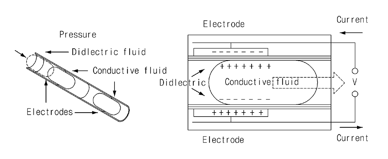
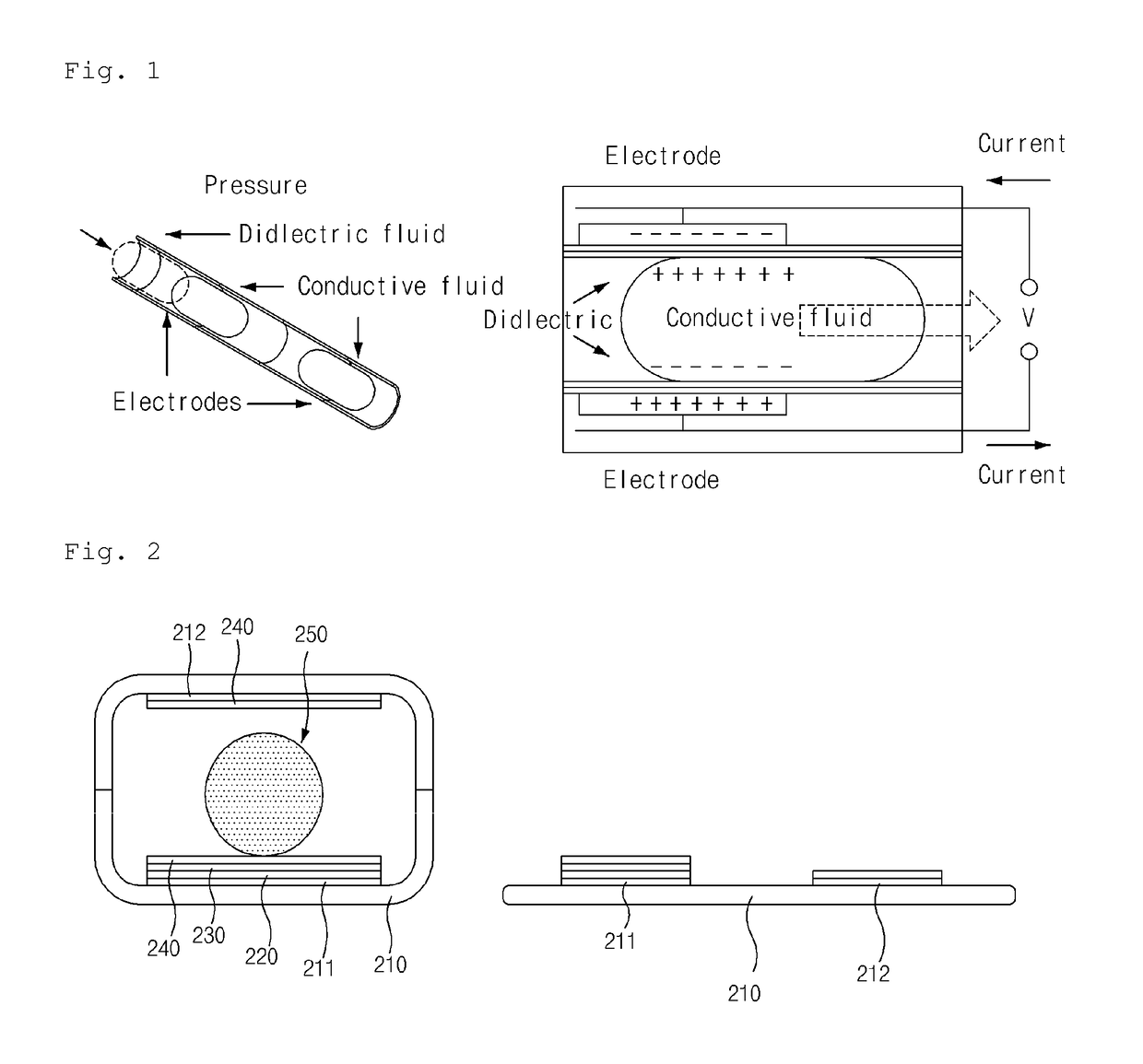
[0037]The advantages and the features of the present invention, and the method for achieving thereof will become apparent with reference to the exemplary embodiments described in detail hereinafter with the accompanying drawings. However, the present invention will not be limited to the exemplary embodiments described hereinafter, but will be implemented in a various different forms, and the exemplary embodiments are provided for the completeness of the disclosure of the present invention and to teach an ordinary person of skill in the art of the scope of the invention completely, and the present invention is only be defined by the scope of the claims. Meanwhile, the terms used in the description are for describing the exemplary embodiments, but not to limit the present invention.

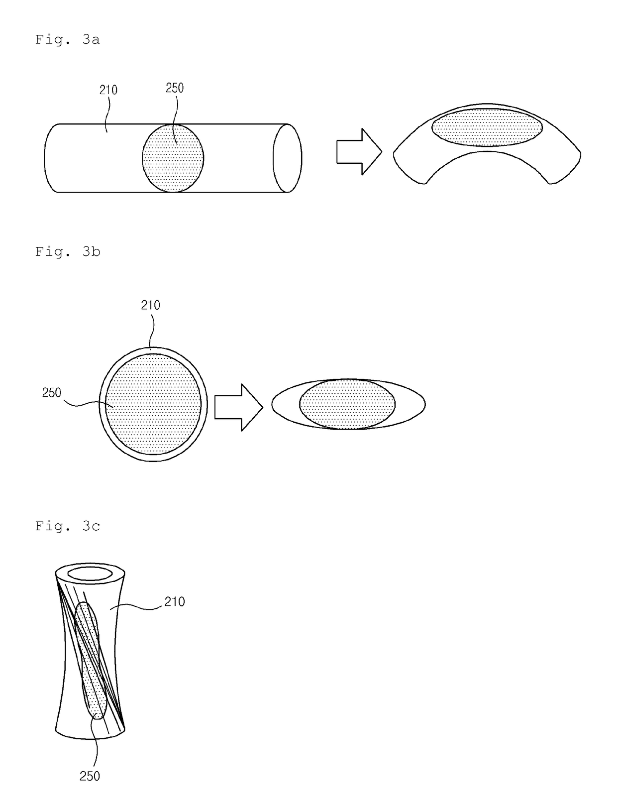
[0038]FIG. 2 is a schematic diagram of a flexible energy conversion device using a liquid according to an exemplary embodiment of the present invention. Referring to FIG. 2, a flexible energy conversion dev...


PUM


Abstract

The present invention relates to a flexible energy conversion device using a liquid, and more specifically, to a method and a device for converting mechanical energy into electric energy by applying an opposite phenomenon of electrowetting, which can change a surface contacting the liquid between one pair of electrodes, and use the change of the surface contacting the liquid to generate electric energy, so as to prevent channel blocking or so that a lubricating layer or electrodes patterned onto a channel in a complicated manner are not required, thereby enabling simplification of the device, reduction of manufacturing cost, and the energy conversion device that is less faulty.

Description

CROSS REFERENCE TO RELATED APPLICATIONS[0001]This application is a National Stage of International Application No. PCT / KR2013 / 010817 filed Nov. 27, 2013, claiming priority based on Korean Patent Application No. 10-2012-0136893 filed Nov. 29, 2012, the contents of all of which are incorporated herein by reference in their entirety.TECHNICAL FIELD[0002]The present invention relates to a flexible energy conversion device using a liquid, and more specifically, to a method and a device for converting mechanical energy into electric energy by applying an opposite phenomenon of electrowetting.BACKGROUND ART[0003]The energy conversion technologies for converting mechanical energy into electrical energy of prior art use a principle that electrical capacitance is being created in the electrode under a dielectric material by varying the contact surface of a liquid metal which is in contact with a dielectric material in accordance with the flow of time.[0004]A method and a device for converting...

Claims


Application Information

Patent Timeline
Patent Type & Authority Patents(United States)
IPC IPC(8): H02N1/08H02N11/00F03G7/00
CPCH02N11/002H02N1/08F03G7/005H02N11/00F03G7/08
Inventor KWON, SOON HYUNGKIM, WON KEUNHAN, CHUL JONGLEE, JEONG NOKIM, YOUN SANGPARK, JUN WOO
Owner KOREA ELECTRONICS TECH INST
Learn More