
Sensory lighting system and method for characterizing an illumination space

a lighting system and sensor technology, applied in the field of illumination systems and methods for characterizing a space for illumination, can solve the problems of sensors and ultrasonic sensors, system rarely used, and lighting system electric energy consumption could be reduced by over 35%

Active Publication Date: 2015-03-05
RENESSELAER POLYTECHNIC INST +1
View PDF5 Cites 33 Cited by
  • Summary
  • Abstract
  • Description
  • Claims
  • Application Information

AI Technical Summary

Benefits of technology

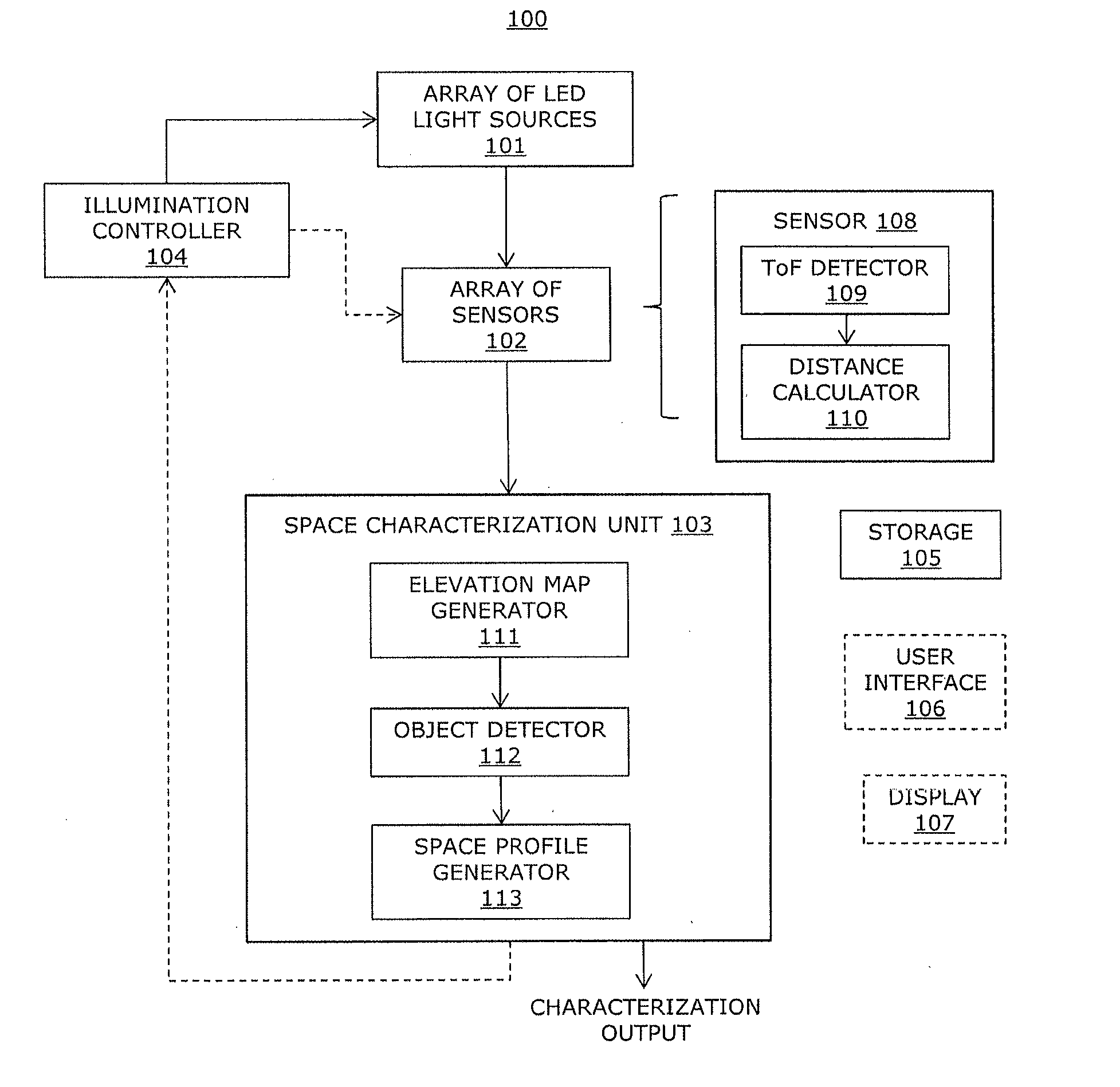
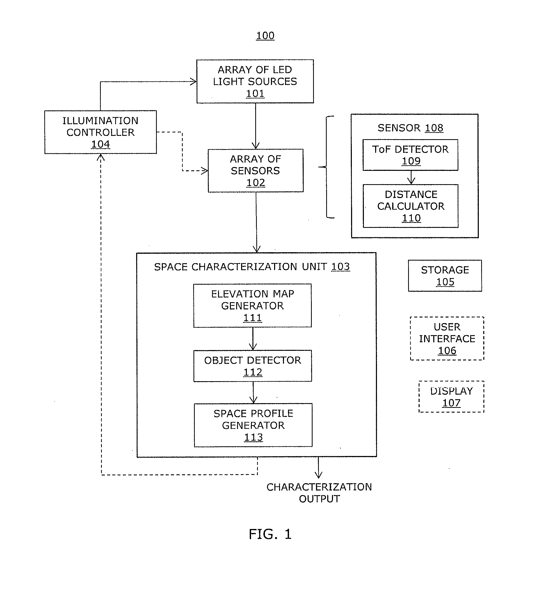
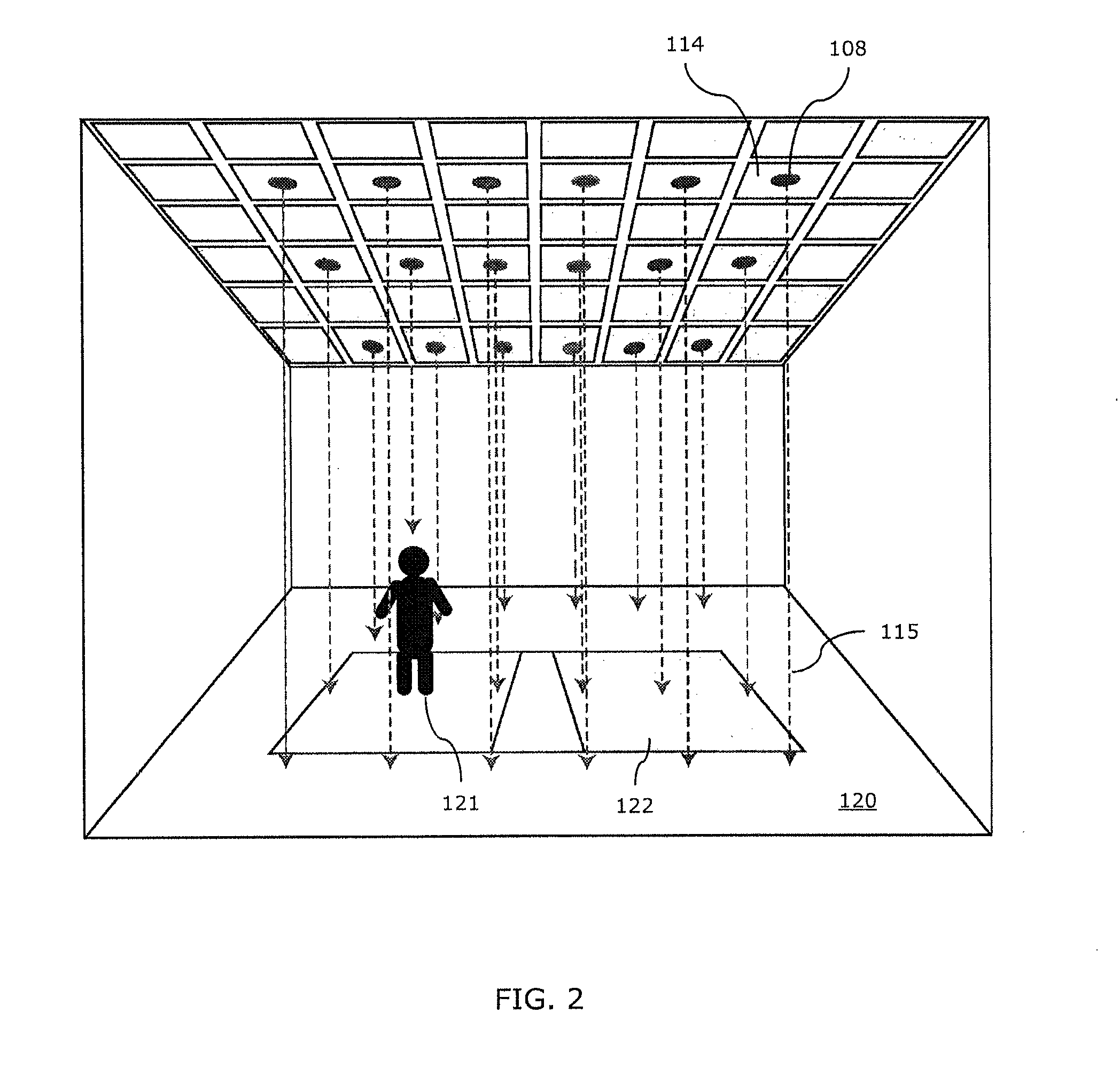
This patent describes an illumination system and a way to figure out what objects are in a space. It uses LED light sources that emit light with a specific pattern, and sensors that detect this pattern when it bounces off objects in the space. By measuring how far the sensors are from the objects, the system can create a map of the space and show where the objects are located. This technology could be useful for creating lighting systems that automatically adjust to the presence of objects, making it easier to light up even when the space is empty or has a lot of objects in it.

Problems solved by technology

While the electrical energy consumed by lighting systems could be reduced by over 35% with the use of advanced lighting control systems, these systems are rarely used as they require frequent calibration to properly adapt to both short (personal lighting needs) and longer term (interior redesign) changes.
Current lighting control based on infrared motion sensors and ultrasonic sensors may be of limited use in lighting control, and the lighting system itself may be blind, as lighting sources may not be able to see the space or objects illuminated by the generated light.
However, there may be privacy concerns associated with the camera systems.
Current approaches for adaptive lighting control may also generate unnecessary complexity through processing large amounts of video information.

Method used


Image

  • Sensory lighting system and method for characterizing an illumination space
  • Sensory lighting system and method for characterizing an illumination space
  • Sensory lighting system and method for characterizing an illumination space

Examples


Embodiment Construction

[0017]Methods for characterizing an illumination space and an illumination system including an array of LED light sources are described.

[0018]Aspects of the invention include exemplary methods for characterizing a space for illumination and an exemplary illumination system. The illumination system may include an array of light sources that, in addition to illuminating a given volume of space, encodes the illumination with a time modulated data signal (i.e., a predetermined modulation pattern), and incorporates a network of widely-separated, low pixel-count light sensors distributed throughout the illumination system. The illumination system may be used for indoor lighting or outdoor lighting. The sensors may measure a time between emission from a given light source (including the time modulated data signal) and the return of some portion of the light containing the data signal. The returned portion of the light may be scattered from one or more surface of objects in the space illumi...


PUM


Abstract

Disclosed herein is an illumination system including an array of LED light sources for emitting light encoded with a modulation pattern, an array of sensors and a space characterization unit. The array of sensors receives emitted light scattered by an object. Each sensor determines a distance between the corresponding light source and the object using the modulation pattern. The space characterization unit uses the distance from each sensor to generate an elevation map indicating a presence of the object.

Description

CROSS REFERENCE TO RELATED APPLICATIONS[0001]This application is related to and claims the benefit of U.S. Provisional Application No. 61 / 687,239 entitled SENSORY LIGHTING SYSTEM filed on Apr. 20, 2012, the contents of which are incorporated herein by reference.STATEMENT REGARDING FEDERALLY SPONSORED RESEARCH[0002]The present invention was supported in part by a grant from the National Science Foundation (Grant No. EEC-0812056) and in part by a grant from NYSTAR (Grant No. C090145). The United States Government may have certain rights to the invention.FIELD OF THE INVENTION[0003]The present invention relates to illumination systems and methods for characterizing a space for illumination.BACKGROUND OF THE INVENTION[0004]Illumination currently consumes approximately 19% of all electrical energy, and many commercial spaces, can consume up to 40% of a typical office building's electrical energy consumption. While the electrical energy consumed by lighting systems could be reduced by ove...

Claims


Application Information

Patent Timeline
Patent Type & Authority Applications(United States)
IPC IPC(8): H05B33/08G01S17/02G01S17/04G06V10/141H05B44/00
CPCG01S17/026H05B33/0854G06T2207/10016G06T2207/10152G06T7/521H05B47/10H05B45/3578H05B47/115H05B45/10Y02B20/40G06V40/103G06V20/52G06V10/141G01S17/04
Inventor KARLICEK, ROBERT F.RADLKE, RICHARD J.LITTLE, THOMAS D,C.BUTALA, PANKIL M.JIA, LI
Owner RENESSELAER POLYTECHNIC INST
Learn More