Rotation detector

a technology of rotation detector and detector, which is applied in the direction of brake system, instruments, transportation and packaging, etc., can solve the problems of difficult to yield high-precision switch outputs, and achieve the effect of reducing the error of position detection

Active Publication Date: 2015-03-05
ALPS ALPINE CO LTD
View PDF4 Cites 7 Cited by
  • Summary
  • Abstract
  • Description
  • Claims
  • Application Information

AI Technical Summary

Benefits of technology

[0018]The rotation detector according to the present invention includes the magnet having the end surfaces which are oriented in the rotating direction and are magnetized to the different magnetic

Problems solved by technology

Disadvantageously, it is difficult to

Method used


Image

  • Rotation detector
  • Rotation detector
  • Rotation detector

Examples


Embodiment Construction

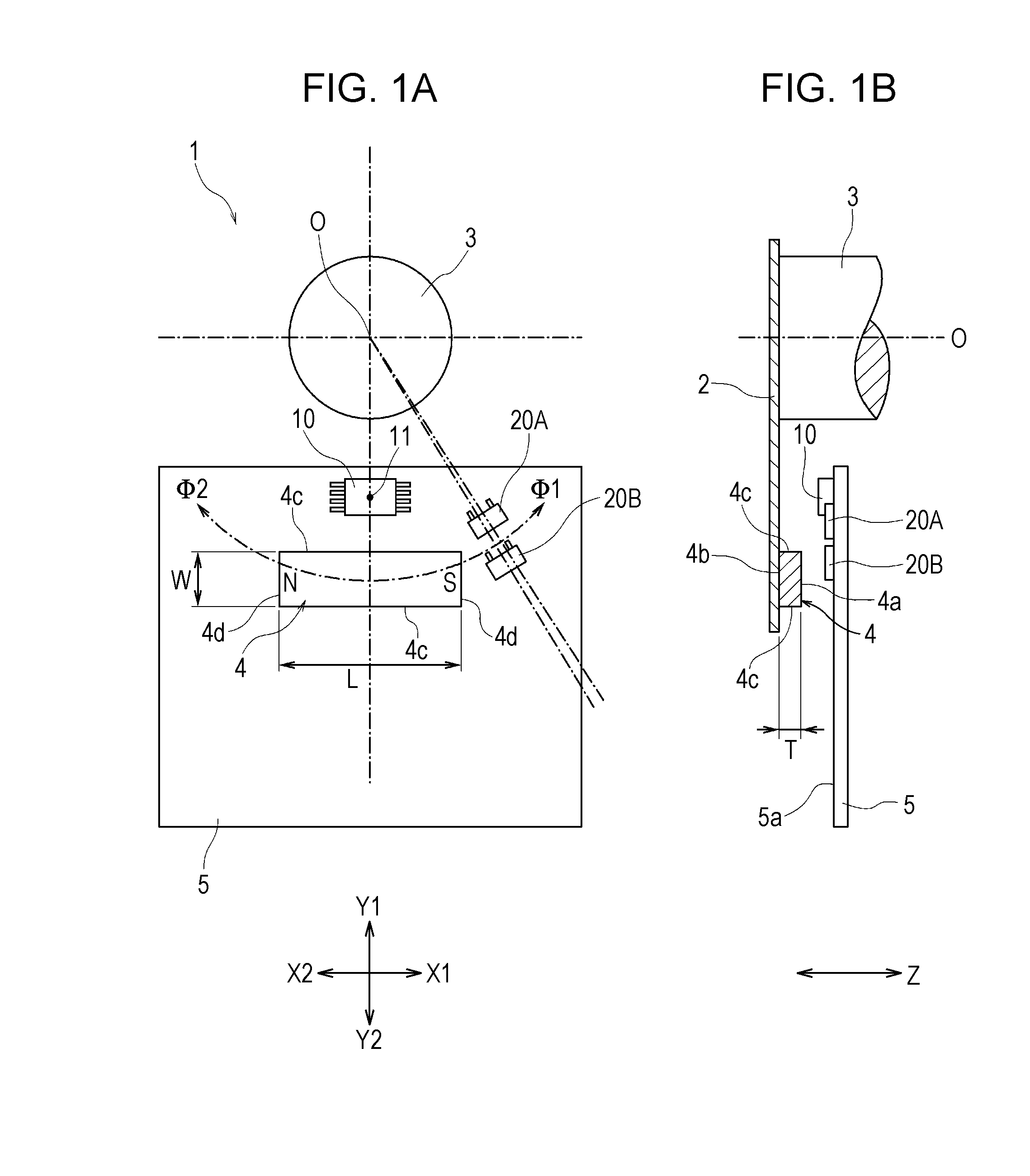
[0036]A rotation detector 1 includes a rotating unit 2 as illustrated in FIG. 1B. The rotating unit 2 is fastened to a rotary shaft 3. The rotating unit 2 and the rotary shaft 3 rotate about a rotation axis O.

[0037]The rotation detector 1 is installed in, for example, a motor vehicle. The rotary shaft 3 is coupled to a brake pedal. When the brake pedal is pressed, the rotary shaft 3 and the rotating unit 2 rotate by an angle depending on the amount of pressing the brake pedal.

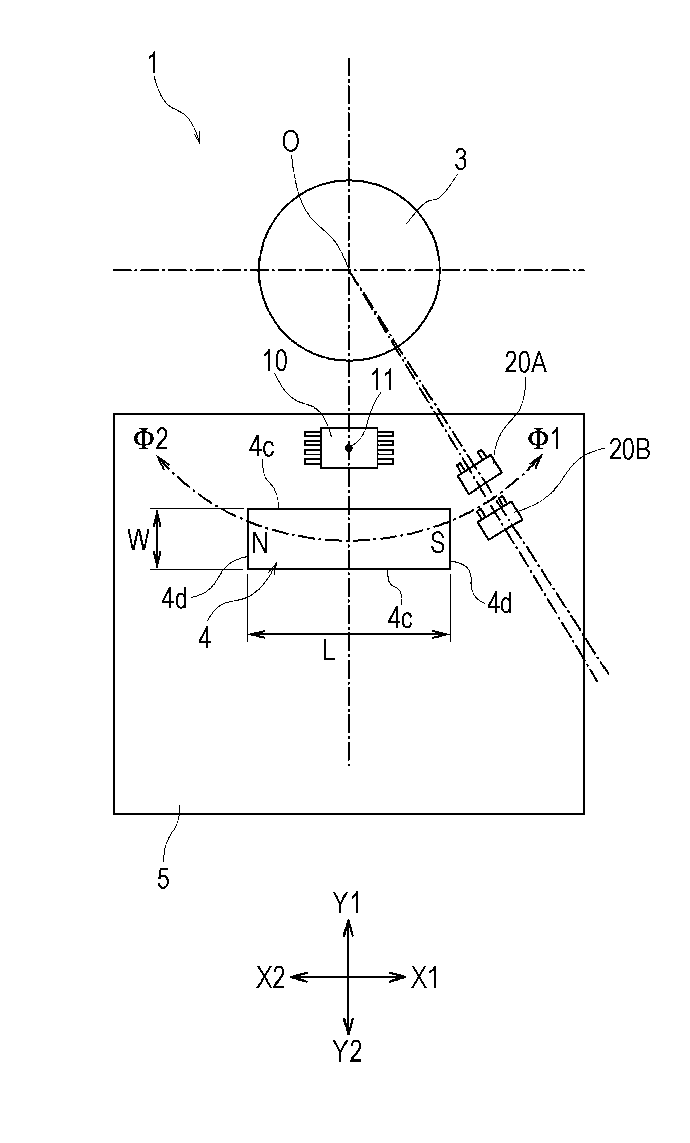
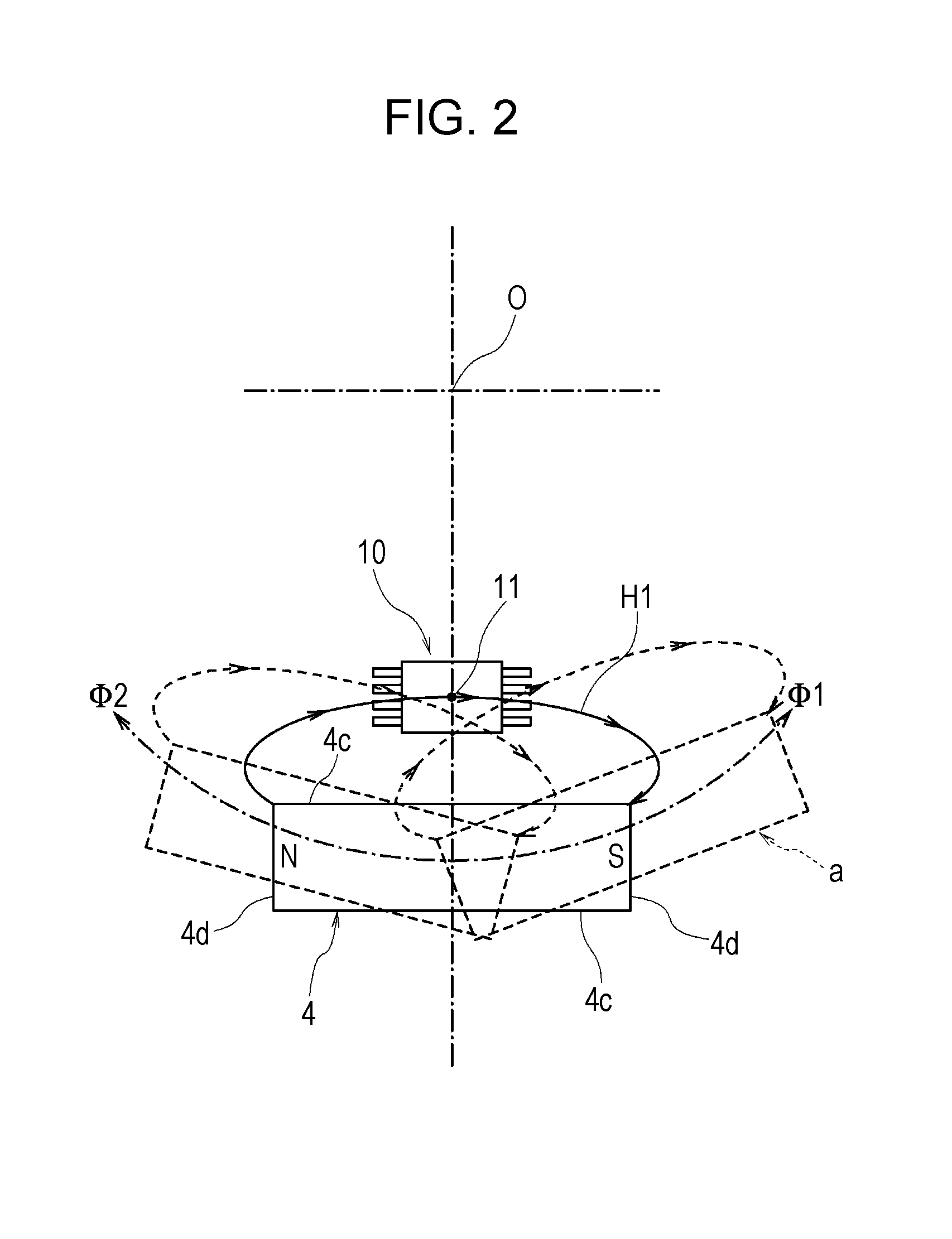
[0038]A magnet 4 is fastened to the rotating unit 2. Preferably, the magnet 4 is rod-shaped and has a flat facing surface 4a and a flat mounting surface 4b such that the facing surface 4a is opposite and parallel to the mounting surface 4b. The magnet 4 is a rectangular solid and has side surfaces 4c, 4c and end surfaces 4d, 4d. The facing surface 4a and the mounting surface 4b are rectangular. The mounting surface 4b of the magnet 4 is fastened to the rotating unit 2.

[0039]The magnet 4 has a length L of 15 mm ...


PUM


Abstract

A rod-shaped magnet is mounted on a rotating unit. The rod-shaped magnet has end surfaces which are oriented in a rotating direction and are magnetized to different magnetic poles. An angle detecting unit including magnetoresistive elements is disposed so as to be offset in a radial direction of a revolution path of the magnet from the revolution path and is configured to detect a change in angle of rotation of the rotating unit by detecting a leakage magnetic field in the vicinity of a side surface of the magnet. Two position detecting units each include magnetoresistive elements and are configured to detect a change in orientation of a magnetic field in the direction of a tangent to the revolution path when facing the rod-shaped magnet and produce a switch output.

Description

CLAIM OF PRIORITY[0001]This application claims benefit of Japanese Patent Application No. 2013-175240 filed on Aug. 27, 2013, which is hereby incorporated by reference.BACKGROUND OF THE INVENTION[0002]1. Field of the Invention[0003]The present invention relates to a rotation detector capable of detecting a change in angle of rotation of a rotating unit and determining whether the rotating unit has rotated to a predetermined position.[0004]2. Description of the Related Art[0005]Detectors detecting a moving magnet with a magnetic detecting element have been used in variety of fields.[0006]Japanese Patent No. 5059772 discloses a magnetic angular position sensor which detects rotation of a cylindrical permanent magnet with two magnetosensitive elements.[0007]This magnetic angular position sensor includes the cylindrical permanent magnet which is attached to an outer circumferential surface of a steering column or a drive shaft. The permanent magnet is radially magnetized. The magnetosen...

Claims


Application Information

Patent Timeline
IPC IPC(8): G01B7/30G01R33/09
CPCG01R33/091G01B7/30B60T7/042G01D5/145G01D2205/73
Inventor ONODERA, TAKASHINAKAMURA, TOKUONOGUCHI, TAKAFUMI
Owner ALPS ALPINE CO LTD
Why Eureka
Try Eureka