
Dental implant member

a technology of dental implants and implants, applied in dental implants, dental surgery, medical science, etc., to achieve the effect of precise manner

Inactive Publication Date: 2015-03-12
WEN SHIH CHENG
View PDF2 Cites 1 Cited by
  • Summary
  • Abstract
  • Description
  • Claims
  • Application Information

AI Technical Summary

Benefits of technology

The present invention is about a dental implant that prevents relative movement between the dental base and the implant body, allowing for one-by-one mounting of a crown on the dental base. This is achieved by designing the lower insert of the dental base and the axial hole in the implant body with truncated cone-shaped sections, which results in interference between the polygonal wall surfaces, thus preventing movement. This also avoids the issue of bottom parts of cylindrical inserts colliding with upper parts of teeth sockets, which can improve dental treatment precision.

Problems solved by technology

As stated above, when a plurality of crowns are mounted on the dental bases respectively, the latter can not be mounted smoothly on the implant bodies, thereby resulting in difficulties during the implanting process.

Method used


Image

  • Dental implant member
  • Dental implant member
  • Dental implant member

Examples


Embodiment Construction

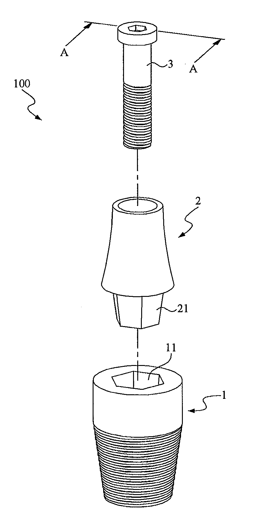
[0030]Referring to FIGS. 5 to 8, wherein FIG. 5 is a partly perspective view of a dental implant member of present invention; FIG. 6 is a partly exploded view of the dental implant member of the present invention; FIG. 7 is a partly exploded and cross-sectional view of the dental implant member of the present invention along Line A-A in FIG. 6; and FIG. 8 is a partly perspective and cross-sectional view of the dental implant member in FIG. 6 of present invention. As illustrated, the dental implant member 100 of the present invention includes an implant body 1, a dental base 2 and a fastener unit 3.

[0031]The implant body 1 is adapted to be implanted into an alveolar bone 200 (jaw bone), and has an axial hole 12 with a truncated cone-shaped section 11 defined by a polygonal inner wall surface. In this embodiment, the truncated cone-shaped section 11 is defined by hexagonal inner wall surfaces.

[0032]The dental base 2 includes a low inset 21 having a truncated cone-shaped section define...


PUM


Abstract

A dental implant member includes an implant body for implanting into an alveolar bone, the implant body having an axial hole with a truncated cone-shaped section defined by a polygonal inner wall surface; a dental base including a low inset having a truncated cone-shaped section defined by a polygonal outer wall surface for inserting into the axial hole in such a manner that the polygonal inner and outer wall surfaces of the implant body and the dental base cooperatively define a fault-tolerance space therebetween; and a fastener unit for extending through the dental base so as to fasten the dental base securely on the implant body.

Description

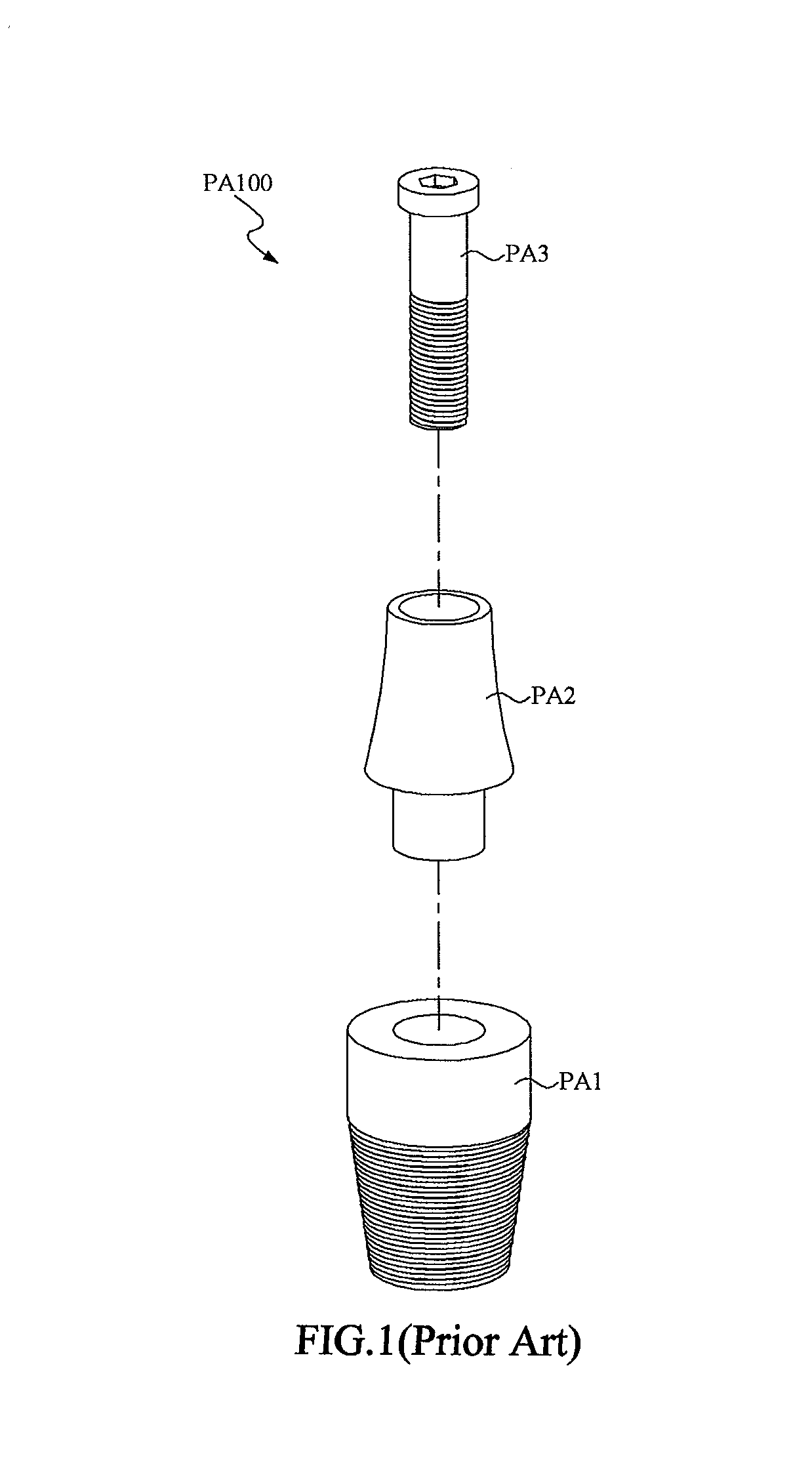
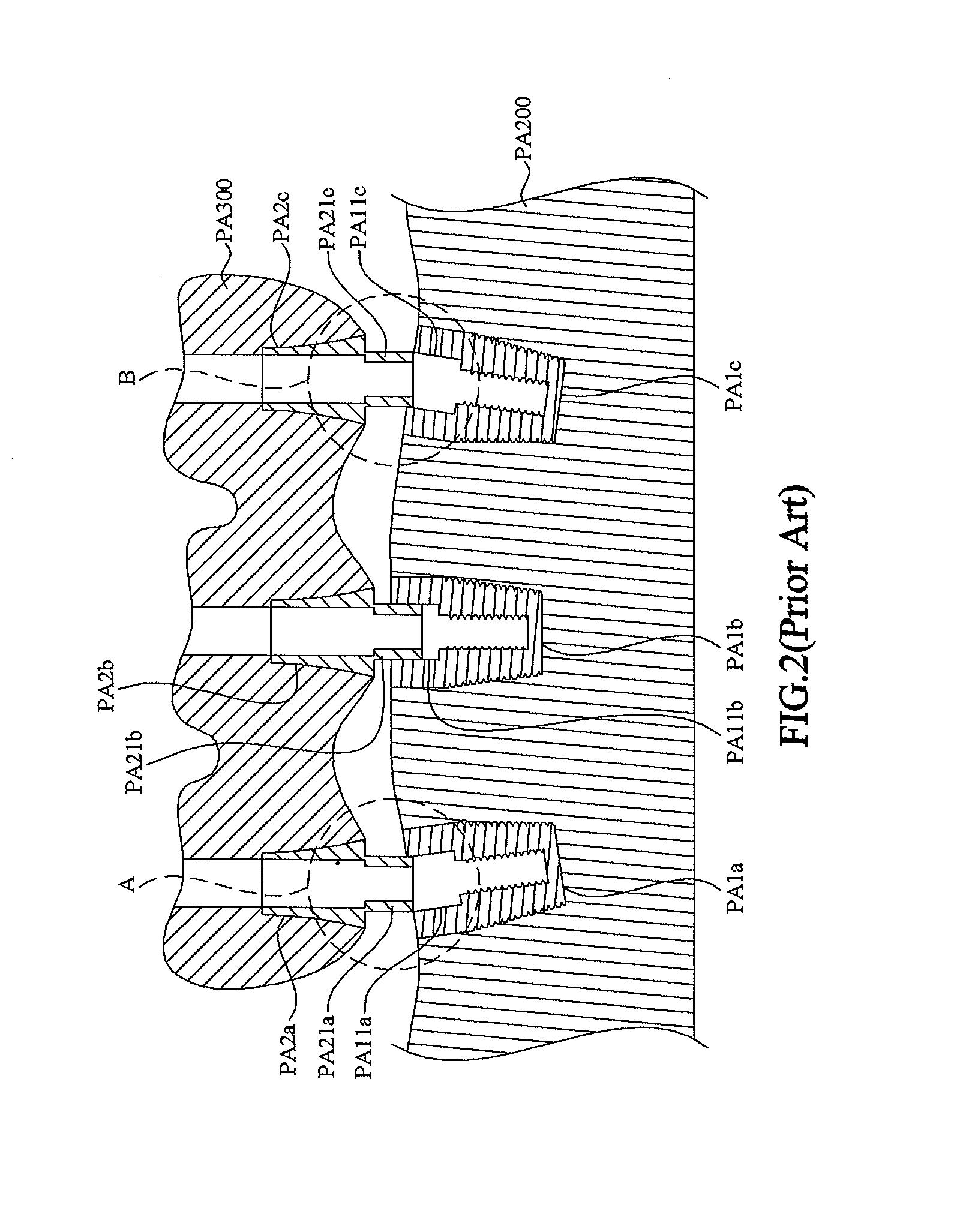
[0001]This application claims the benefits of the Taiwan Patent Application Serial NO. 102217103, filed on Sep. 11, 2013 the subject matter of which is incorporated herein by reference.BACKGROUND OF THE INVENTION[0002]1. Field of the Invention[0003]The present invention relates to a dental implant member, more particularly to dental implant member including a truncated cone-shaped insert and an implant body having an axial hole with a truncated cone-shaped section for receiving the truncated cone-shaped insert therein.[0004]2. Description of the Prior Art[0005]Referring to FIGS. 1 to 2B, wherein FIG. 1 is a partly exploded view of a dental implant member of the prior art; FIG. 2 is a cross-sectional view of the dental implant member of the prior art; FIG. 2A is an enlarged view of an encircled portion (A) in FIG. 2 and FIG. 2B is an enlarged view of an encircled portion (B) in FIG. 2. As illustrated in FIG. 1, the prior art dental implant member PA100 generally includes an implant b...

Claims


Application Information

Patent Timeline
Patent Type & Authority Applications(United States)
IPC IPC(8): A61C8/00
CPCA61C8/0068A61C8/0069A61C8/006
Inventor WEN, SHIH-CHENG
Owner WEN SHIH CHENG
Learn More