Refrigerant hose with metal foil layer

a technology of refrigerant hoses and metal foils, applied in the field of refrigerant hoses, can solve the problems of poor adhesion between the metal foil layer and the surrounding polymer layer, and achieve the effects of high resistance to permeation, good flexibility, and high strength

Inactive Publication Date: 2015-03-19
CONTITECH USA INC
View PDF21 Cites 11 Cited by
  • Summary
  • Abstract
  • Description
  • Claims
  • Application Information

AI Technical Summary

Benefits of technology

[0013]The air conditioning hose of this invention offers an extremely high level of resistance to permeation by refrigerants, including carbon dioxide, as well as good flexibility, high strength, the ability to bend to small radii without kinking, and the ability to be tightly coupled to refrigeration device components in a leak proof fashion. These objectives are accomplished in the practice of this invention by incorporating a layer of a metal foil into the air conditioning hose structure. The layer of metal foil acts to inhibit permeation by refrigerants, including carbon dioxide, to keep the refrigerant for escaping through the hose and into the atmosphere.

Problems solved by technology

One traditional problem with the incorporation of layers of metal foils into hose structures is poor adhesion between the layer of metal foil and surrounding polymeric layers.

Method used


Image

  • Refrigerant hose with metal foil layer
  • Refrigerant hose with metal foil layer

Examples


Embodiment Construction

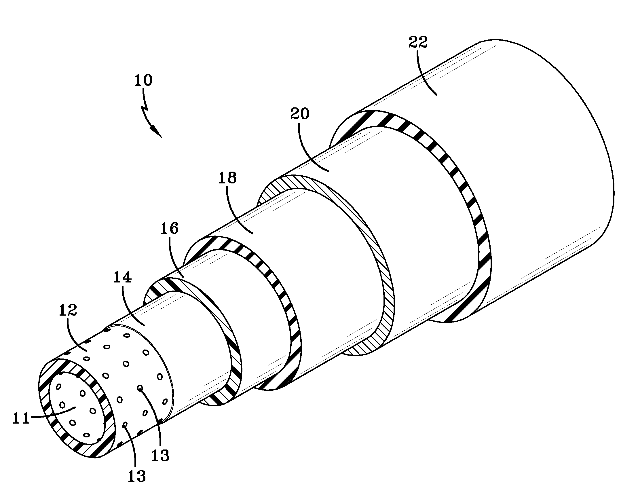
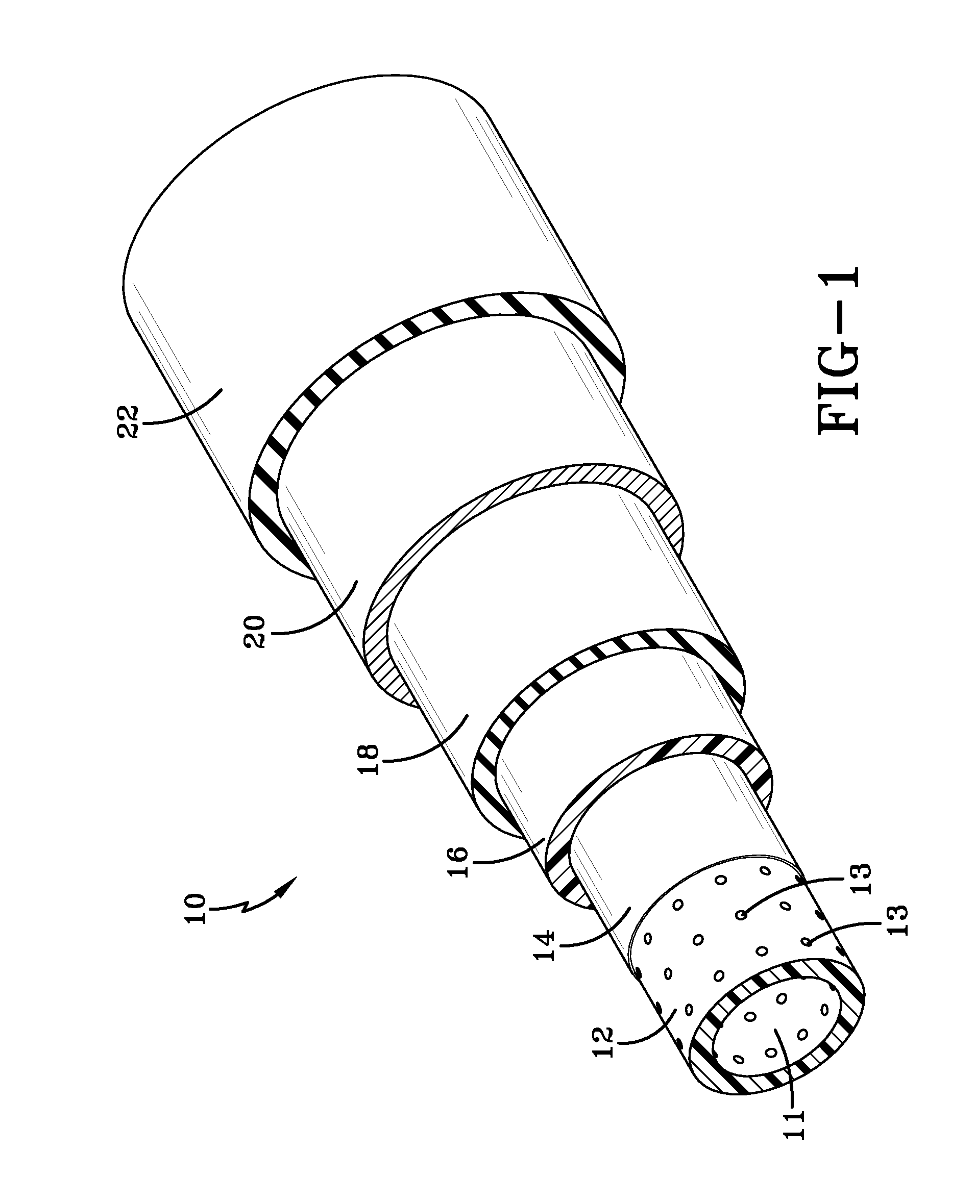
[0017]The refrigerant hose 10 of the present invention is illustrated in FIG. 1 and typically has an inside diameter of about 2 mm to 10 mm. The refrigerant hose of this invention will more typically have an inside diameter of 4 mm to 8 mm and will frequently have a diameter of 5 mm to 7 mm. The hose 10 has a core layer 12, relative to the radial direction of the hose and the longitudinal hose axis. The core layer 12 is formed from a plastic material which is typically an ethylene vinyl alcohol (EVOH), a polyamide (nylon), or a polyolefin, such as polyethylene (PE) or polypropylene (PP) and is the innermost layer of the hose. This tubular inner core layer defines the lumen 11 of the hose and is typically about 0.01 inch (0.25 mm) to 0.1 inch (2.5 mm) thick. In most cases the core layer is 0.02 inch (0.51 mm) to 0.08 inch (2.03 mm) thick with it commonly being 0.03 inch (0.76 mm) to 0.05 inch (1.27 mm) thick. The tubular inner core layer 12 is frequently referred to in the art as sim...


PUM


Abstract

The air conditioning hose of this invention offers an extremely high level of resistance to permeation by refrigerants, including carbon dioxide, as well as good flexibility, high strength, the ability to bend to small radii without kinking, and the ability to be tightly coupled to refrigeration device components in a leak proof fashion. The subject invention specifically discloses a refrigerant hose comprising: (a) a core layer, wherein the core layer is comprised of a thermoplastic polymer, and wherein the core layer includes perforations; (b) a metal foil layer which is situated over the core layer; (c) plastic layer which is situated over the metal foil layer; (d) a rubber layer which is situated over the plastic layer, (e) a reinforcing layer which is situated over the rubber layer; and (f) a cover layer which is situated over the reinforcing layer, wherein the cover layer is comprised of a rubbery polymer.

Description

[0001]This application claims the benefit of U.S. Provisional Patent Application Ser. No. 61 / 878,932, filed on Sep. 17, 2013. The teachings of U.S. Provisional Patent Application Ser. No. 61 / 878,932 are incorporated herein by reference in their entirety.FIELD OF THE INVENTION[0002]The present invention is directed to a hose suitable for use in the conveyance of refrigerants which are under high pressure for use in vehicle, industrial, and residential refrigerant systems, such as automotive air conditioning systems. This hose is of particular value in air conditioning systems that utilize carbon dioxide as the refrigerant. The refrigerant hose of this invention provides good flexibility coupled with a high level of resistance to permeation by refrigerants by virtue of including a layer of a metal foil, such as aluminum foil.BACKGROUND OF THE INVENTION[0003]Hoses are used for transporting refrigerants in vehicle air conditioning systems, and in industrial and residential refrigerant s...

Claims


Application Information

Patent Timeline
Patent Type & Authority Applications(United States)
IPC IPC(8): F16L11/04F16L11/12
CPCF16L11/045F16L2011/047F16L11/12F16L11/085
Inventor HENRY, BRIAN
Owner CONTITECH USA INC
Why Eureka
Try Eureka