
Pivotally Mounted Window and Screen Assembly

Inactive Publication Date: 2015-03-26
WALTER RUDOLPH
View PDF11 Cites 15 Cited by
  • Summary
  • Abstract
  • Description
  • Claims
  • Application Information

AI Technical Summary

Benefits of technology

The present invention is a new and improved pivotally mounted window and screen assembly that can be used to position the window in various ways, making it easier to clean the window from inside the building. Additionally, this assembly can be easily removed and replaced.

Problems solved by technology

These devices, however, do not disclose a pivotally mounted window and screen assembly that may be secured in an open position via a stopping mechanism.
While the pivotal movement of these devices allow a user to access clean the exterior side of a window, these devices are limited in that they cannot fully swing or open.
Additionally, none of the foregoing devices disclose a screen or a mesh panel wherein the same is used to prevent debris or insects from coming into the building while allowing fresh air to circulate.
While Alcanzare discloses a window frame adapted to pivot about the vertical axis of the frame, it is limited in the fact that the window frame swings in only one direction.
Furthermore, Alcanzare does not disclose a hinged window frame and a screen that is pivotally mounted on the window frame.
The Kvasnes device does not disclose a pivotally mounted screen, and is not designed for use with the same.
While the device of Hirayama allows a user to access the exterior surface of the window, the Hirayama device is limited in that it cannot swing inward.
Furthermore, the device of Hirayama does not include a screen that filters debris and dust when the window is open.
While the device of Ohman allows the user to pivot or rotate the window, the Ohman device is limited in the fact that it requires a groove or a channel on the window frame to guide the bushings thereon.

Method used


Image

  • Pivotally Mounted Window and Screen Assembly
  • Pivotally Mounted Window and Screen Assembly
  • Pivotally Mounted Window and Screen Assembly

Examples


Embodiment Construction

[0034]References is made herein to the attached drawings. Like reference numerals are used throughout the drawings to depict like or similar elements of the pivotally mounted window and screen assembly. For the purposes of presenting a brief and clear description of the present invention, the preferred embodiment will be discussed as used for providing access to the exterior surface of the window from inside of a building. The figures are intended for representative purposes only and should not be considered to be limiting in any respect.

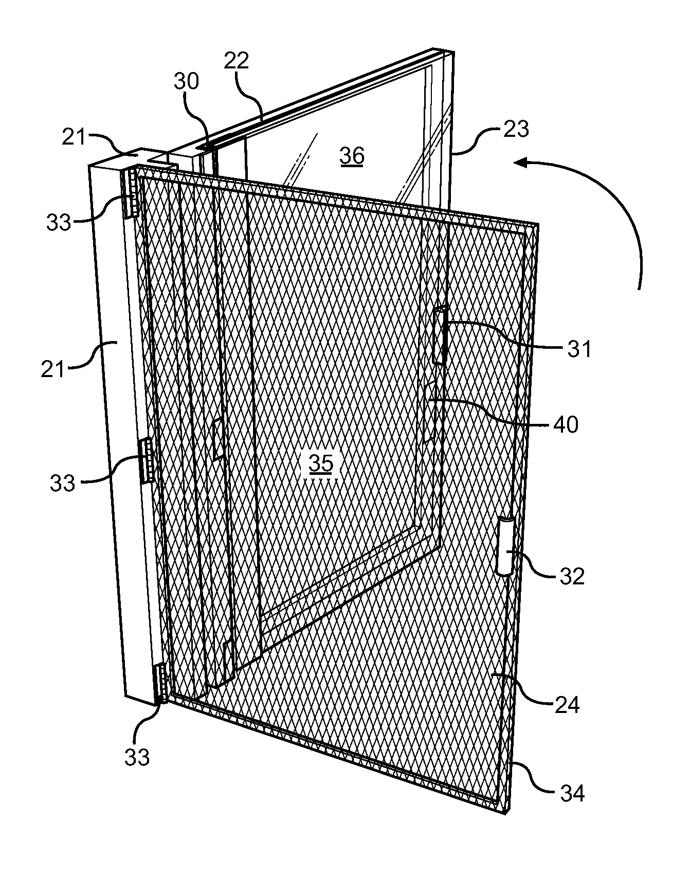
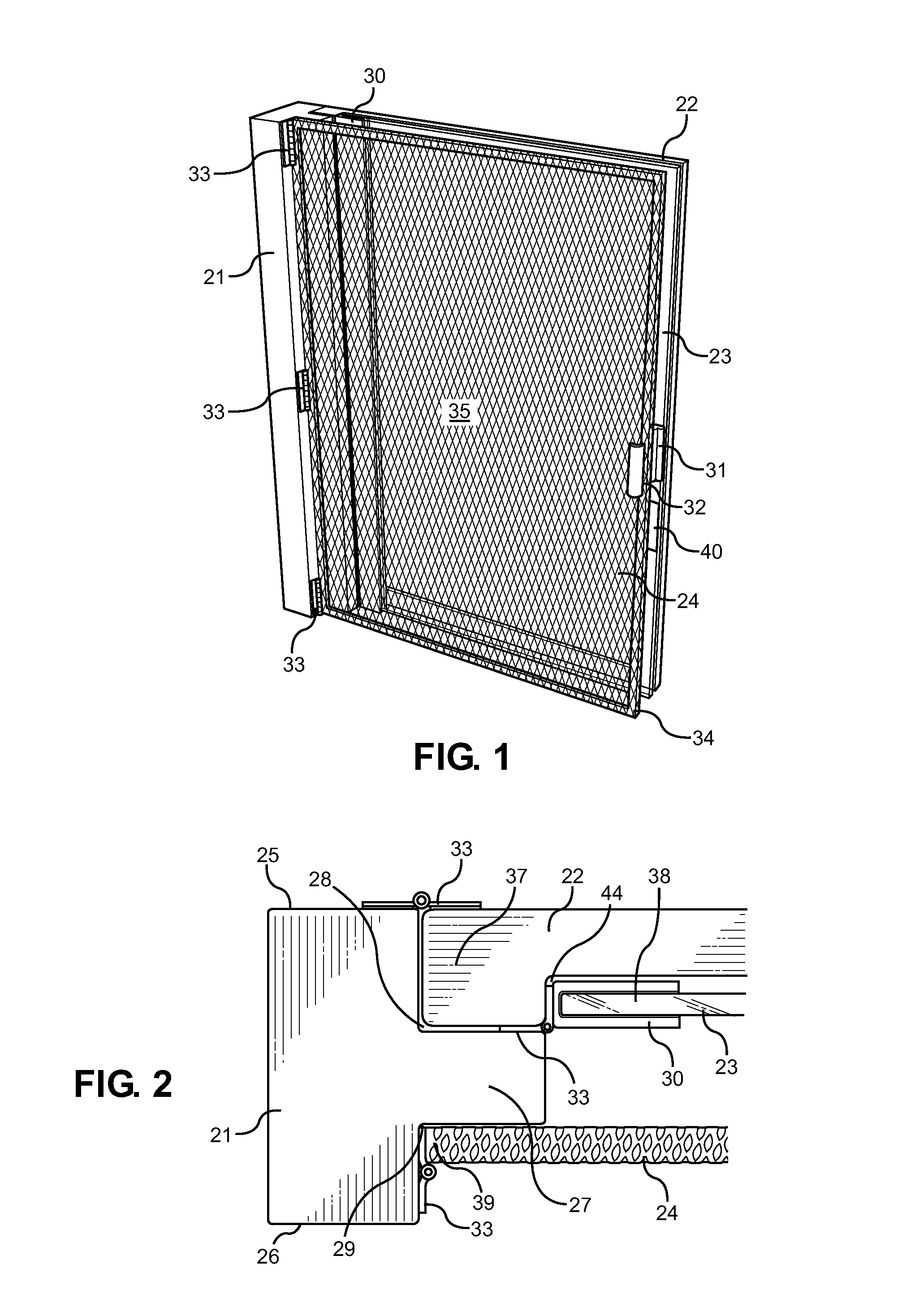
[0035]Referring now to FIGS. 1 and 2, there are shown views of the pivotally mounted window and screen assembly of the present invention in a closed position. The present invention comprises a vertical support bar 21, a pivotally mounted screen 24 and a window frame 22 having a window sash 23 mounted thereto. In the illustrated embodiments, the vertical support bar 21 and the window frame 22 is composed of wood. In other embodiments, however, the su...


PUM


Abstract

Disclosed is a pivotally mounted window and screen assembly. The device includes a T-shaped vertical support bar that is hingedly attached to a screen and a window frame, in which a window sash is mounted. The window frame is adapted to swing outward, while the screen is adapted to swing inward so that the window sash is unobstructed and can swing open the full 180 degree range relative to the vertical support bar. The present invention further includes a locking mechanism that secures the window sash and the screen in an open position. In this way, a user can open the window to access and clean the exterior side of the window without extending any portion of the body outside of a building. The present invention may be constructed to be installed into any window opening of a building.

Description

CROSS REFERENCE TO RELATED APPLICATION[0001]This application claims the benefit of U.S. Provisional Application No. 61 / 880,419 filed on Sep. 20, 2013. The above identified patent application is herein incorporated by reference in its entirety to provide continuity of disclosure.BACKGROUND OF THE INVENTION[0002]1. Field of the Invention[0003]The present invention relates to a reversible window. More specifically, the present invention pertains to a pivotally mounted window and screen assembly. The window and screen assembly of the present invention is pivotally mounted to a vertical support bar via pins and brackets to increase accessibility to an exterior surface of the window. In this way, the present invention allows homeowners and building owners to clean window exteriors while safely inside of a building.[0004]Clean windows can be important to the aesthetic appeal of a building and clean windows are also important for practical purposes. Cleaning windows, however, can be an ardu...

Claims


Application Information

Patent Timeline
IPC IPC(8): E06B9/01E06B3/36E06B9/02E06B9/00E06B3/26
CPCE06B9/01E06B9/00E06B3/26E06B2009/002E06B3/36E06B2009/015E06B9/02E06B5/003E06B2003/346E06B9/04
Inventor WALTER, RUDOLPH
Owner WALTER RUDOLPH
Features
  • Generate Ideas
  • Intellectual Property
  • Life Sciences
  • Materials
  • Tech Scout
  • Unparalleled Data Quality
  • Higher Quality Content
  • 60% Fewer Hallucinations
Learn More