Control apparatus and control method for diesel engine

Active Publication Date: 2015-03-26
NISSAN MOTOR CO LTD
View PDF10 Cites 2 Cited by
  • Summary
  • Abstract
  • Description
  • Claims
  • Application Information

AI Technical Summary

Benefits of technology

[0003]However, there are cases where some of the increased fuel adheres to glow plugs, prohibiting a temperature increase in these glow plugs. Furthermore, the increased rotational speed of the engine also suppresses the temperature increase in th

Problems solved by technology

However, there are cases where some of the increased fuel adheres to glow plugs, prohibiting a temperature increase in these glow plugs.
Furthermore, the increased rotational speed of the engine also suppresses the temperature increase in the

Method used


Image

  • Control apparatus and control method for diesel engine
  • Control apparatus and control method for diesel engine
  • Control apparatus and control method for diesel engine

Examples


first embodiment

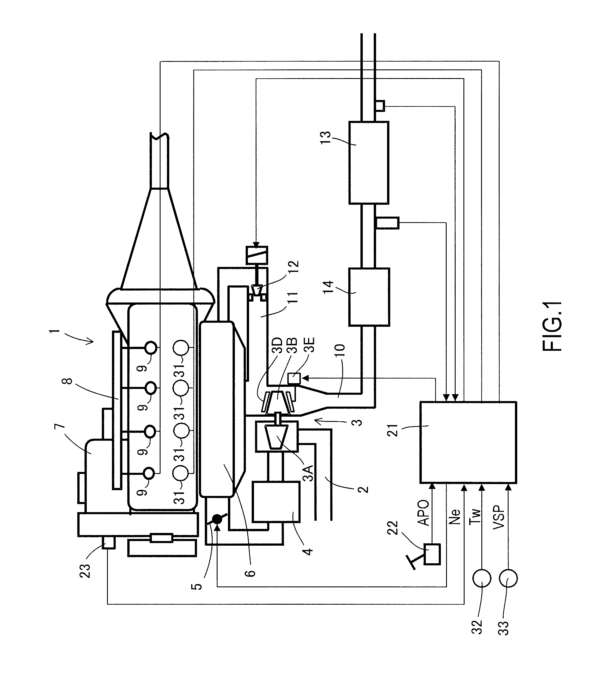
[0030]FIG. 1 shows a schematic configuration of a control apparatus for a diesel engine according to a first embodiment of the present invention.

[0031]A variable nozzle type of turbo charger 3 includes an inlet compressor 3A, an exhaust turbine 3B, and a shaft 3C that couples them together.

[0032]Intake air is supercharged by an inlet compressor 3A provided in an intake passage 2 of a diesel engine 1, and cooled by an intercooler 4. Then, the intake air passes through an intake throttle valve 5, and flows into respective cylinders through a collector 6.

[0033]A high-pressure fuel pump 7 increases the pressure of fuel, and delivers it to a common rail 8. Then, fuel injecting valves 9 in the cylinders directly inject the fuel into the cylinders. The high-pressure fuel pump 7, the common rail 8, and the fuel injecting valves 9 configure a common rail type of fuel injecting apparatus. The air flowing into the cylinders and the fuel injected from the fuel injecting valves 9 are compressed ...

second embodiment

[0097]FIG. 8 is a flowchart of a second embodiment. The same step numbers are assigned to the same parts as those in the first embodiment as in FIG. 7

[0098]The second embodiment differs from the first embodiment in Step S31.

[0099]At Step S31, the controller determines whether or not the temperature of the cooling water Tw is lower than a preset value [° C.] during the idle operation immediately after the cold start. This preset value is the lower temperature limit of the cooling water, which can reduce the rotational fluctuation at an early stage while preventing an unstable rotation during the idle operation immediately after the cold start. The preset value is defined in advance with adaptation. If the determination result is “Yes,” the controller moves the processing to Step S16. If the determination result is “No,” the controller moves the processing to Step S20.

[0100]This second embodiment also enables an early transition to a stable idle operation immediately after a cold star...

third embodiment

[0101]As described above, studies have been conducted on diesel engines with lower compression ratios than conventional ones. When a compression ratio decreases, a temperature of a compression end also decreases. Accordingly, an ignition performance upon an engine start and idle combustion stability are worsened, in particular, at low temperatures. Therefore, using an idle-up function facilitates an early transition to a stable idle operation. This idle-up function can also operate a supercharger. Operating the supercharger decreases the penetrating power of fuel, as described later, thus reducing a risk that the fuel will adhere to the glow plugs.

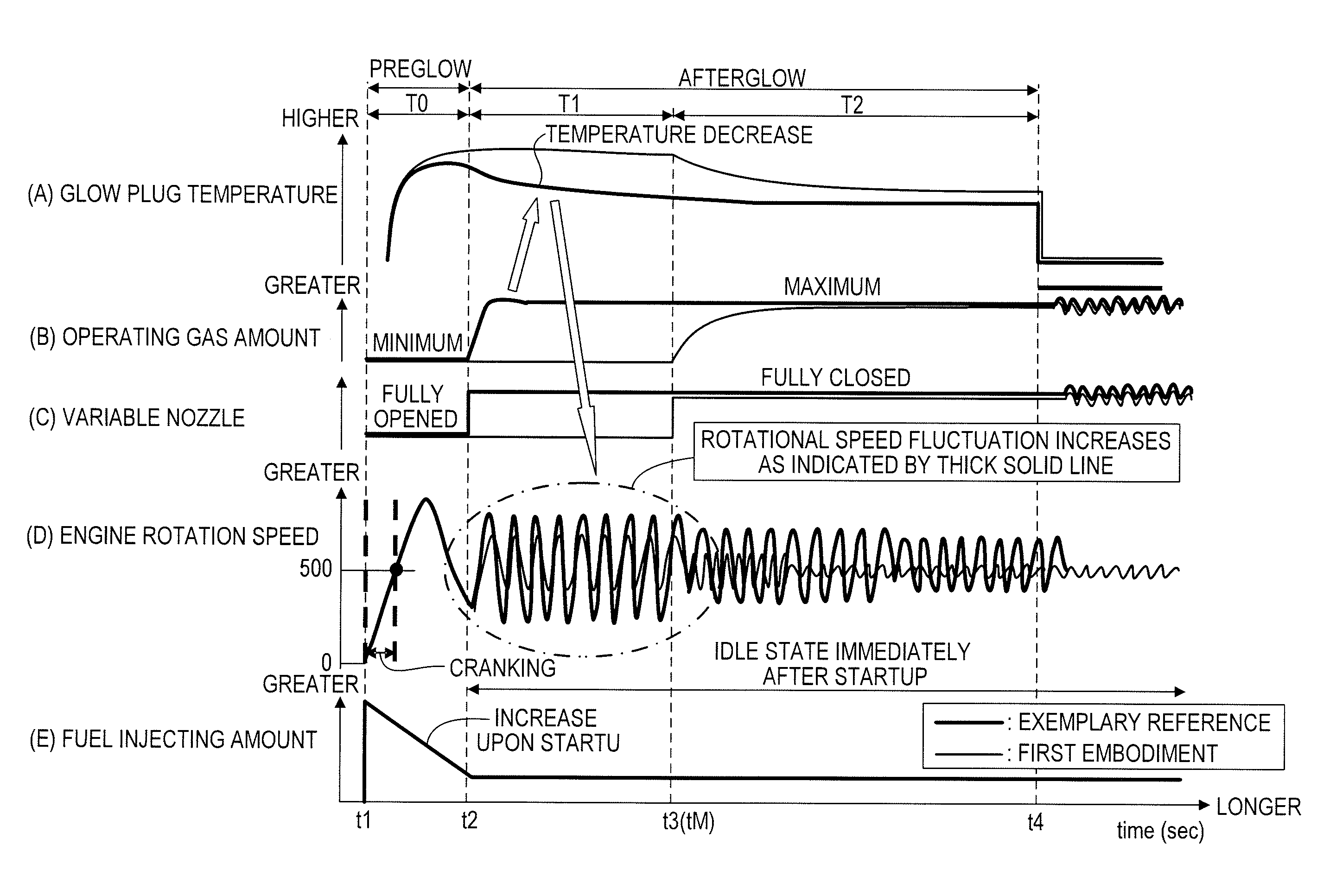
[0102]In the first and second embodiments, when the condition is satisfied, the variable nozzle or the like is changed step by step in order to increase the amount of the operating gas. This achieves an early transition to a stable idle operation immediately after a cold start without causing excessive idle instability.

[0103]As a result of...


PUM


Abstract

A control apparatus for a diesel engine includes a neighboring temperature estimating section which estimates a temperature of a neighborhood of a glow plug that heats an interior of a cylinder upon startup, and a supercharging pressure control section which controls a supercharging pressure in such a way that a rotation fluctuation of the engine does not increase, on the basis of the estimated temperature of the neighborhood of the glow plug.

Description

TECHNICAL FIELD[0001]This invention relates to a control apparatus and control method for a diesel engine.BACKGROUND ART[0002]Combustion becomes more unstable immediately after a cold start than during a normal operation. That is, the rotations of diesel engines fluctuate more widely. JP2001-263131A discloses a technique for injecting a larger amount of fuel during an idle operation immediately after a cold start than during a normal operation. In this way, the rotational speed of the engine increases, becoming stable earlier.SUMMARY OF INVENTION[0003]However, there are cases where some of the increased fuel adheres to glow plugs, prohibiting a temperature increase in these glow plugs. Furthermore, the increased rotational speed of the engine also suppresses the temperature increase in the glow plugs, because the inflow of cold outside air (air) increases. If the temperature of the glow plugs does not increase, an unstable combustion state continues. In addition, increasing the fuel...

Claims


Application Information

Patent Timeline
IPC IPC(8): F02D41/00F02P19/02F02D41/06F02D41/14
CPCF02D41/0007F02D41/064F02P19/025F02D41/14F02B37/24F02D23/00F02D23/02F02D35/026F02D41/08F02D41/086F02D41/1401F02D2041/1437F02D2200/021F02D2200/0406F02D2200/0414F02P19/02Y02T10/12
Inventor NISHIZAWA, TORUIIO, SHUICHIOHGA, KIYOSHINAKAYAMA, RYOTAYAMAZAKI, TAKASHIIMAOKA, YOSHIHIROOHMURA, YASUSHIUEHARA, ISSHOUNAKANO, MASAHIKOHASEGAWA, MANABU
Owner NISSAN MOTOR CO LTD
Why Eureka
Try Eureka