Fuser Assembly with Automatic Media Width Sensing and Thermal Compensation

a technology of fuser assembly and thermal compensation, which is applied in the direction of instruments, electrographic process devices, optics, etc., can solve the problems of reduced throughput of printers, overheating problems, and hotter fuser parts

Inactive Publication Date: 2015-03-26
LEXMARK INT INC
View PDF12 Cites 36 Cited by
  • Summary
  • Abstract
  • Description
  • Claims
  • Application Information

AI Technical Summary

Benefits of technology

[0013]Embodiments of the present disclosure provide systems for controlling temperature of portions of a heater of a fuser assembly that would all

Problems solved by technology

When a to-be-printed media sheet has a width narrower than the width of the widest media supported by the printer, overheating problems may occur because the media sheet removes heat from the fuser only in the portion of the fuser contacting the media.
As the portion of the fuser beyond the width of the media sheet does not lose any heat to the media sheet, such portion of the fuser becomes hotter than the portion contacting the media sheet and can be damaged due to high temperature.
By doing so, however, throughput of the printer is reduced when printing media sheet sizes that are less than the widest supported media size leading to reduced perfor

Method used


Image

  • Fuser Assembly with Automatic Media Width Sensing and Thermal Compensation
  • Fuser Assembly with Automatic Media Width Sensing and Thermal Compensation
  • Fuser Assembly with Automatic Media Width Sensing and Thermal Compensation

Examples


Embodiment Construction

[0028]It is to be understood that the present disclosure is not limited in its application to the details of construction and the arrangement of components set forth in the following description or illustrated in the drawings. The present disclosure is capable of other embodiments and of being practiced or of being carried out in various ways. Also, it is to be understood that the phraseology and terminology used herein is for the purpose of description and should not be regarded as limiting. The use of “including,”“comprising,” or “having” and variations thereof herein is meant to encompass the items listed thereafter and equivalents thereof as well as additional items. Unless limited otherwise, the terms “connected,”“coupled,” and “mounted,” and variations thereof herein are used broadly and encompass direct and indirect connections, couplings, and mountings. In addition, the terms “connected” and “coupled” and variations thereof are not restricted to physical or mechanical connec...


PUM


Abstract

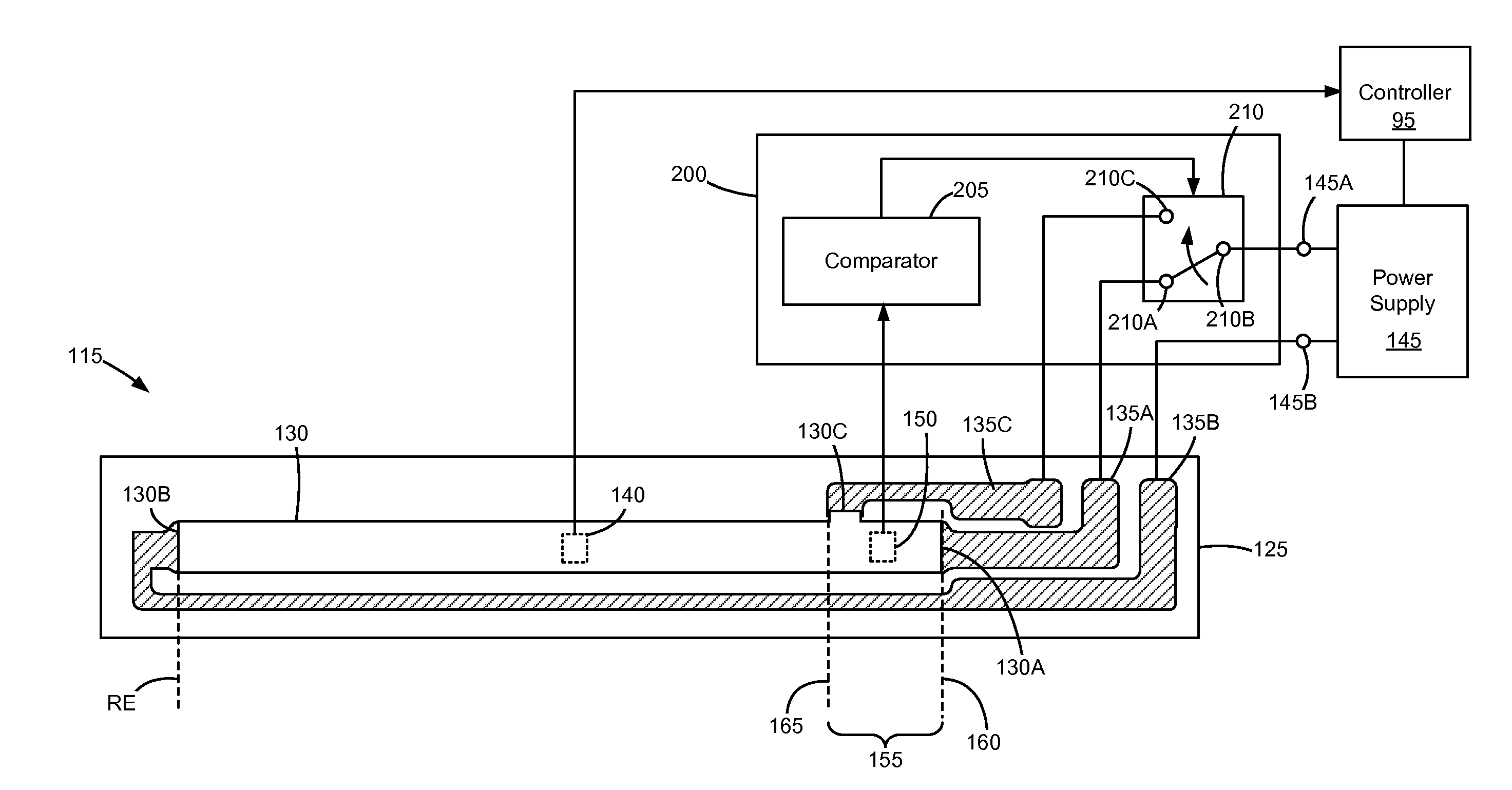
A fuser assembly for an electrophotographic imaging device includes a heater including a substrate, a resistive trace disposed and running along a length of the substrate for generating heat for fusing toner to a sheet of media when a current is passed therethrough, and at least three conductors for passing current through the resistive trace. The at least three conductors include a first conductor connected to a first end portion of the resistive trace, a second conductor connected to a second end portion of the resistive trace, and a third conductor connected to the resistive trace at a location between the first end portion and the second end portion thereof. A temperature sensor senses a temperature of an edge segment of the substrate. Based upon the temperature sensed, circuitry selects between the first conductor and the third conductor for passing current through the resistive trace.

Description

CROSS REFERENCES TO RELATED APPLICATIONS[0001]Pursuant to 35 U.S.C. §119, this application claims the benefit of the earlier filing date of Provisional Application Ser. No. 61 / 883,036, filed Sep. 26, 2013, entitled “Fuser with Automatic Paper Width Sensing and Thermal Compensation,” the content of which is hereby incorporated by reference herein in its entirety.STATEMENT REGARDING FEDERALLY SPONSORED RESEARCH OR DEVELOPMENT[0002]None.REFERENCE TO SEQUENTIAL LISTING, ETC[0003]None.BACKGROUND[0004]1. Field of the Disclosure[0005]The present disclosure relates generally to controlling a fuser assembly in an electrophotographic imaging device, and particularly to maintaining temperature levels in the fuser assembly to allow for multiple media widths to print at full speed without overheating any portion of the fuser assembly.[0006]2. Description of the Related Art[0007]In an electrophotographic (EP) imaging process used in printers, copiers and the like, a photosensitive member, such as...

Claims


Application Information

Patent Timeline
IPC IPC(8): G03G15/20
CPCG03G15/2039G03G15/2042
Inventor BUSH, CRAIG PALMERCAO, JICHANGDAY, MICHAEL C.LUCAS, RUSSELL EDWARDMEADE, ALEXANDER DOUGLASREAM, GREGORY L.
Owner LEXMARK INT INC
Why Eureka
Try Eureka