Bauteilsystem einer turbomaschine

a technology of aircraft turbine and component system, which is applied in the direction of liquid fuel engine, leakage prevention, motors, etc., can solve the problems of comparatively poor sealing of segment joints, correspondingly high manufacturing and repair costs, and substantial assembly and disassembly expenditure, so as to improve sealing and simplify and improve assembly. the effect of economic and practicality

Active Publication Date: 2015-03-26
MTU AERO ENGINES GMBH
View PDF6 Cites 7 Cited by
  • Summary
  • Abstract
  • Description
  • Claims
  • Application Information

AI Technical Summary

Benefits of technology

The present invention provides a component system that has improved sealing, is simpler and more economical to assemble, and achieves the sealing through the use of overlapping elements on mutually abutting surfaces. The overlapping elements are integrated into the component segments, and no detachable parts are required. This simplifies the manufacturing and assembly process, and reduces the tolerance chain for leakage gaps. The system has at least three overlapping elements, with at least two on each component segment, and they alternate in their configuration to reduce the impact of tolerances between abutment surfaces. The overlapping elements can be metallurgically bonded to the component segments, eliminating the need for separate parts.

Problems solved by technology

In all of the known design variations, the sealing action is greatly influenced by the various tolerance chains, however, so that only a comparatively poor sealing of the segment joints can be achieved.
Moreover, the use of individual sealing plates leads to a substantial assembly and disassembly expenditure, for example, and thus to correspondingly high manufacturing and repair costs.

Method used


Image

  • Bauteilsystem einer turbomaschine
  • Bauteilsystem einer turbomaschine
  • Bauteilsystem einer turbomaschine

Examples


Embodiment Construction

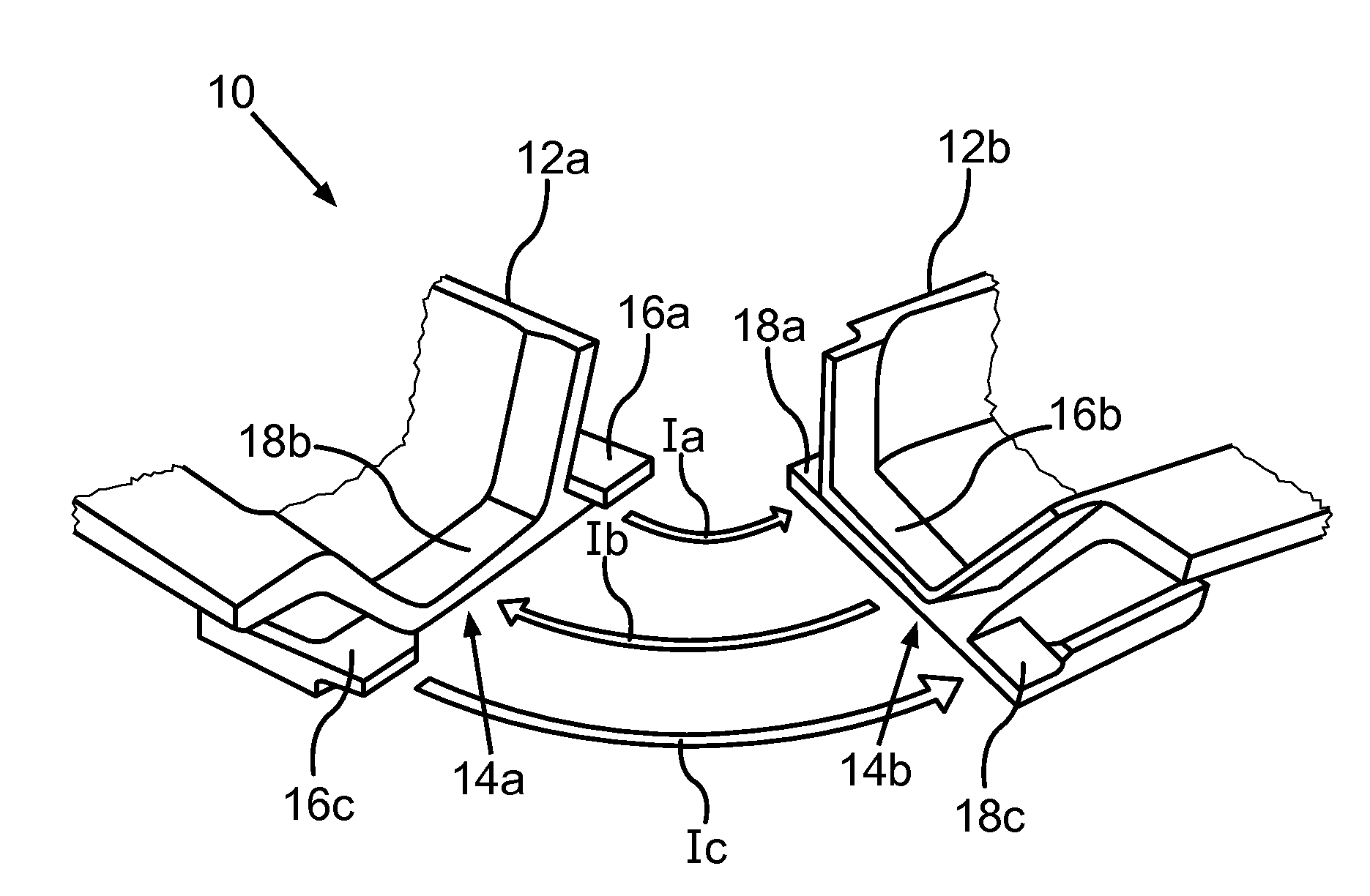
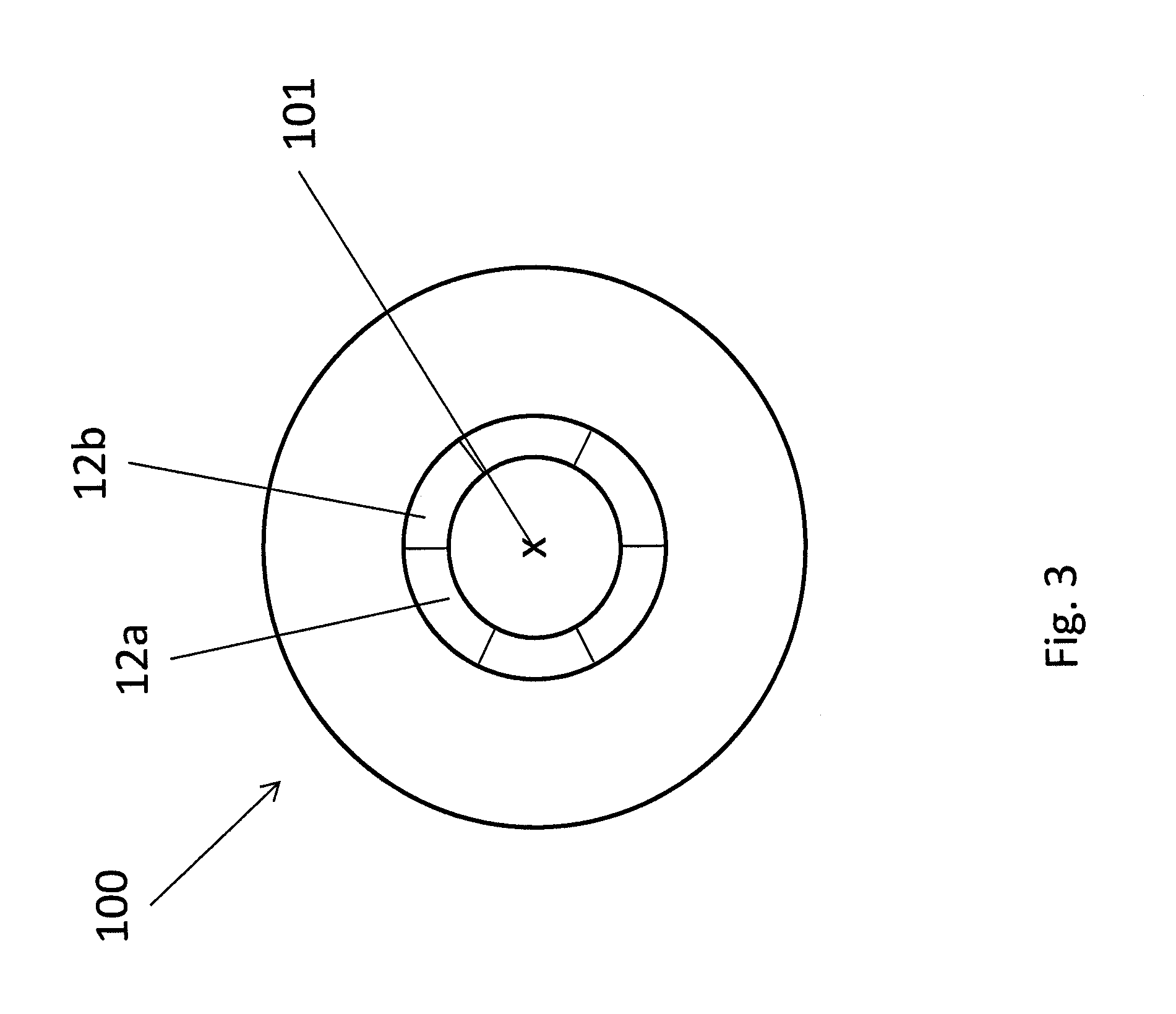
[0023]FIG. 1 shows a schematic perspective view of a component system 10 in accordance with a first exemplary embodiment of the present invention. Component system 10 includes a plurality of component segments, of which merely one first component segment 12a and a second component segment 12b are shown in a cutaway view. In the present case, component system 10 is configured as a blade ring of an aircraft turbine and includes other component segments which are designed analogously to illustrated component segments 12a, 12b and complement one another to form a ring. For assembly purposes, the component segments are annularly configured about an axis 101 of a rotor of the aircraft engine 100 as shown schematically in FIG. 3, so that, in each case, an abutment surface 14a of first component segment 12a and an abutment surface 14b of the second component segment 12b abut against each other. Abutment surfaces 14a, 14b are provided in each case at the narrow sides of component segments 12...


PUM

PropertyMeasurementUnit
distancesaaaaaaaaaa
surface areaaaaaaaaaaa
stableaaaaaaaaaa

Abstract

A component system of a turbine engine including a first component segment and a second component segment configurable in a ring segment shape, so that at least one abutment surface of the first component segment and an abutment surface of the second component segment abut against each other; together, the first component segment and the second component segment including at least three overlapping elements for sealing a gap between the abutment surfaces. In the case of mutually abutting abutment surfaces, each overlapping element overlapping radially with the respective other component segment. At least two of the overlapping elements are configured on the first component segment, while at least one of the overlapping elements is configured on the second component segment. In the case of mutually abutting abutment surfaces, the overlapping element of the second component segment is axially configured between the overlapping elements of the first component segment.

Description

[0001]This claims the benefit of German Patent Application DE 10 2013 219 024.7, filed Sep. 23, 2013 and hereby incorporated by reference herein.[0002]The present invention relates to a component system of a turbine engine, in particular of an aircraft turbine. The present invention also relates to a method for assembling such a component system, as well as to a turbine engine having such a component system.BACKGROUND[0003]The European Patent Application EP 1 013 788 A1 describes a component system of an aircraft turbine that includes a plurality of component segments, which are each formed as shroud segments and are configured in a housing annularly about a rotor of the aircraft engine. Each component segment includes two mutually opposing abutment surfaces, which, in the assembled state, abut against an associated abutment surface of the respective adjacent component segment. To prevent or at least reduce a passage of hot gases through a gap located between the abutment surfaces o...

Claims


Application Information

Patent Timeline
Patent Type & Authority Applications(United States)
IPC IPC(8): F01D11/00
CPCF05D2230/60F01D11/001F01D9/04F01D11/005F01D25/24F05D2230/30F05D2230/61Y10T29/4932
Inventor HESS, THOMASFELDMANN, MANFRED
Owner MTU AERO ENGINES GMBH
Why Eureka
Try Eureka