Robot calibrating apparatus and robot calibrating method, and robot apparatus and method of controlling robot apparatus

a robot body and calibrating method technology, applied in the direction of electric programme control, program control, instruments, etc., can solve the problems of insufficient suppression of errors by conventional coordinate calibrating methods, preventing the improvement of accuracy in controlling the position and orientation of the robot body, and operation errors occur. achieve the effect of improving accuracy in controlling the position and orientation

Active Publication Date: 2015-03-26
CANON KK
View PDF2 Cites 23 Cited by
  • Summary
  • Abstract
  • Description
  • Claims
  • Application Information

AI Technical Summary

Benefits of technology

[0008]It is an object of the present invention to provide a robot calibrating apparatus and a robot calibrating method, and a robot apparatus and a method of controlling a robot apparatu...

Problems solved by technology

In actuality, an operational error occurs owing to mechanical error or bending at an arm.
There are further errors that are other than operational error and are specific to a robot body; these errors include an assembly...

Method used


Image

  • Robot calibrating apparatus and robot calibrating method, and robot apparatus and method of controlling robot apparatus
  • Robot calibrating apparatus and robot calibrating method, and robot apparatus and method of controlling robot apparatus
  • Robot calibrating apparatus and robot calibrating method, and robot apparatus and method of controlling robot apparatus

Examples


first embodiment

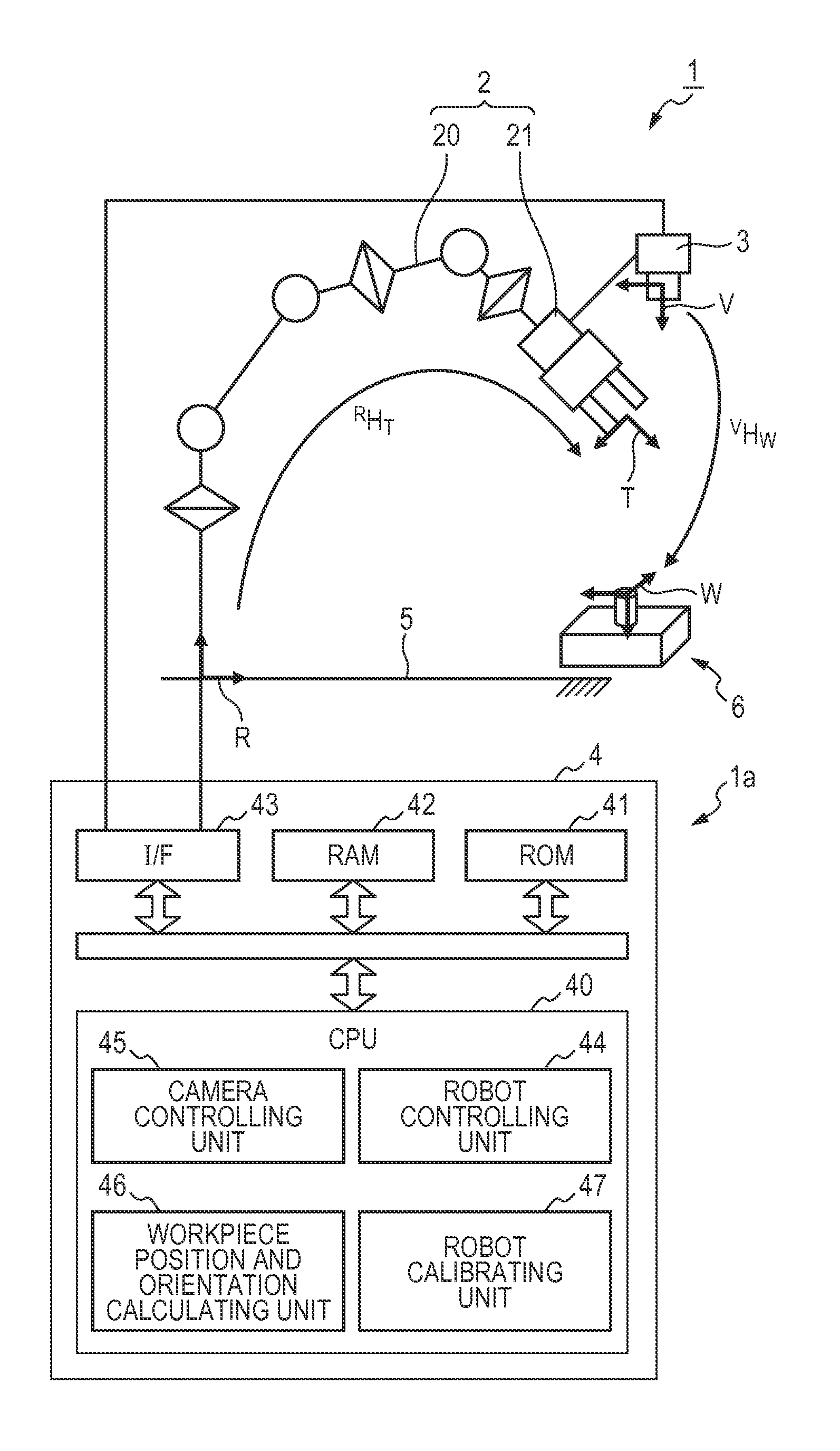
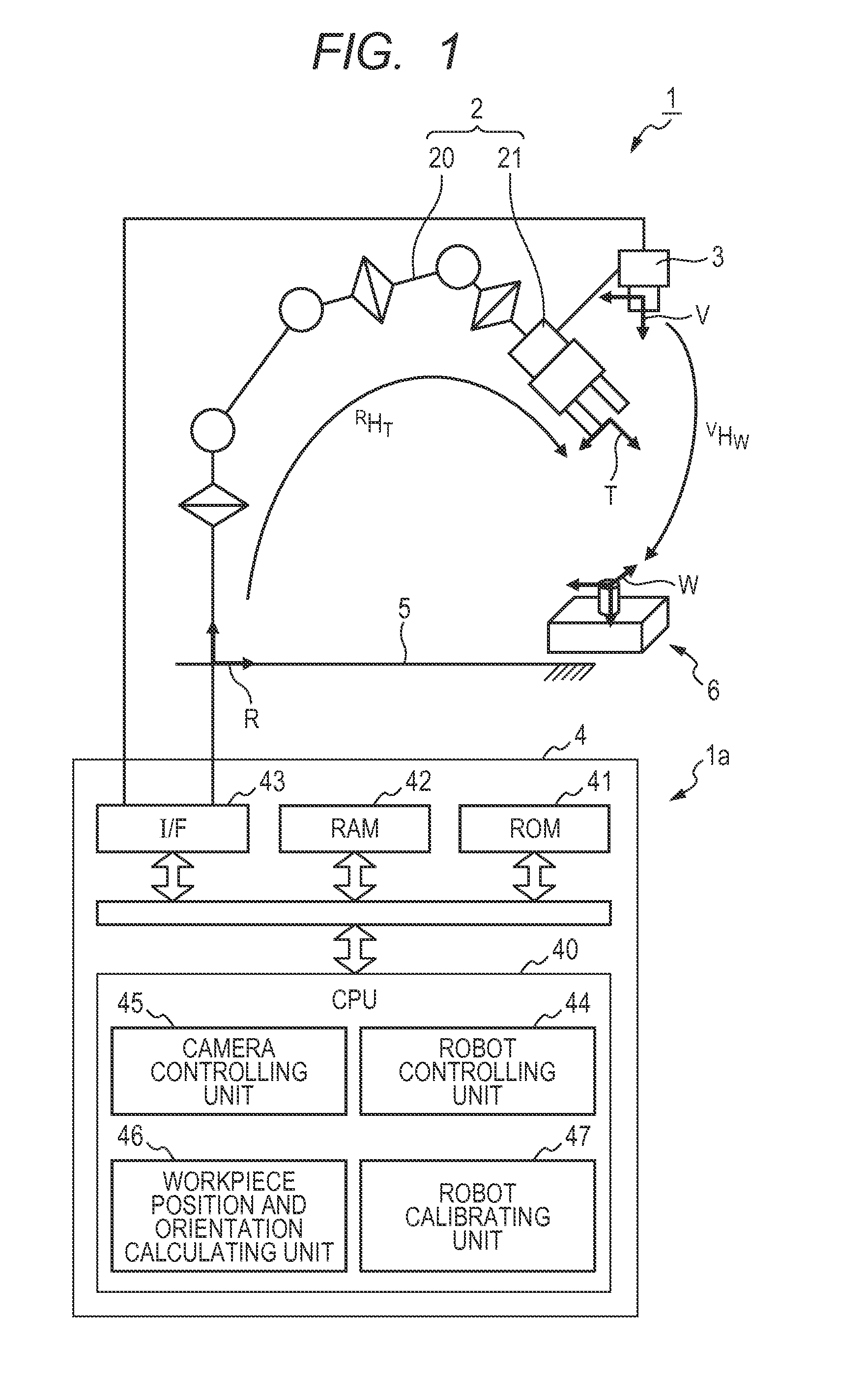
[0024]Before description of a robot system 1 of this embodiment, the definitions of representation of expressions in this specification are described. In this specification, six-degree-of-freedom positions and orientations of a multi-jointed arm 20, a hand 21, a camera 3 and a workpiece 6, which configure the robot system 1, are represented in a three-dimensional coordinate system. Relativized positions and orientations in any two coordinate systems are represented by a coordinate transformation matrix (homogeneous transformation matrix).

[0025]First, a coordinate transformation matrix that represents a relativized position and orientation from any coordinate system A to any coordinate system B is represented as AHB. The relativized position and orientation indicated by the coordinate transformation matrix AHB is also represented as a relativized position and orientation AHB. For instance, in this embodiment, as illustrated in FIG. 1, the relativized position and orientation of an af...

second embodiment

[0108]Next, a robot system 101 according to the second embodiment of the present invention is described. As illustrated in FIG. 7 and FIG. 8, the robot system 101 includes a robot apparatus 101a and a robot calibrating unit 47. Unlike the first embodiment, in this robot apparatus 101a, a camera 103 is not arranged on the robot body 102 but is fixed to and supported by an upper support base 50, which is positioned relative to a platform 5, which is fixed to the base end part of a robot body 102. Furthermore, unlike the first embodiment, in the robot apparatus 101a, the calibrating plate 10 is not supported by the platform 5 but is supported by a support member 22, which is positioned relative to the hand 21. Other hardware configurational elements are analogous to the elements of the first embodiment. Accordingly, the same symbols identical to the symbols of the first embodiment are assigned to the respective elements. The description thereof is omitted.

[0109]Procedures where the for...


PUM


Abstract

A robot calibrating apparatus calibrating a command value for a robot body 2 whose position and orientation is controlled based on the command value, includes an operating unit configured to calculate a calibrating function of calibrating the command value, based on the difference between an ideal position and orientation of the robot body 2 and an actual position and orientation of the robot body 2. The ideal position and orientation is operated based on a command value RHTcom for calibration used during calibration or on a control result value which is a result of control according to the command value. The actual position and orientation is operated based on a measurement value RHT′meas for calibration acquired by a camera 3 arranged at a prescribed relative position and orientation with respect to the robot body 2 during the robot body 2 being controlled according to the command value for calibration.

Description

BACKGROUND OF THE INVENTION[0001]1. Field of the Invention[0002]The present invention relates to a robot calibrating apparatus and a robot calibrating method in a robot apparatus that includes a multi-jointed arm driven through control on multiple joints and utilizes a visual sensor, and a robot apparatus and a method of controlling a robot apparatus.[0003]2. Description of the Related Art[0004]Conventionally, a robot apparatus has become widespread which includes a vertical multi-jointed arm, an end effector (hereinafter, called a robot body) and a controlling apparatus for controlling these elements, and further includes a visual sensor (hereinafter, also called a camera) attached to a tip end part of the arm. In this robot apparatus, an object, such as a workpiece, is measured through the camera, and the controlling apparatus operates the position and orientation of the object from a measurement result and controls the position and orientation of the robot body based on the posit...

Claims


Application Information

Patent Timeline
IPC IPC(8): B25J9/16
CPCB25J9/1697B25J9/1692G05B2219/39008G05B2219/39044G05B2219/39045
Inventor SUZUKI, HIDEAKIAMANO, SHINGO
Owner CANON KK
Why Eureka
Try Eureka