

Vehicle seat
a technology for seats and vehicles, applied in the field of vehicles seats, can solve the problems of increasing material costs and complicated parts control, and achieve the effect of preventing restricting the deformation of the rail
- Summary
- Abstract
- Description
- Claims
- Application Information
AI Technical Summary
Benefits of technology
Problems solved by technology
Method used
Image

Examples
Embodiment Construction
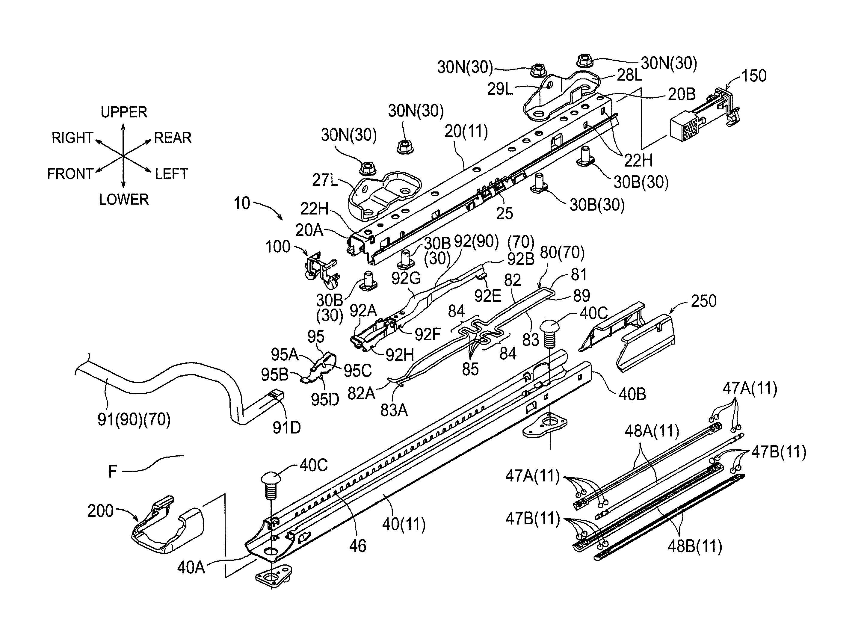
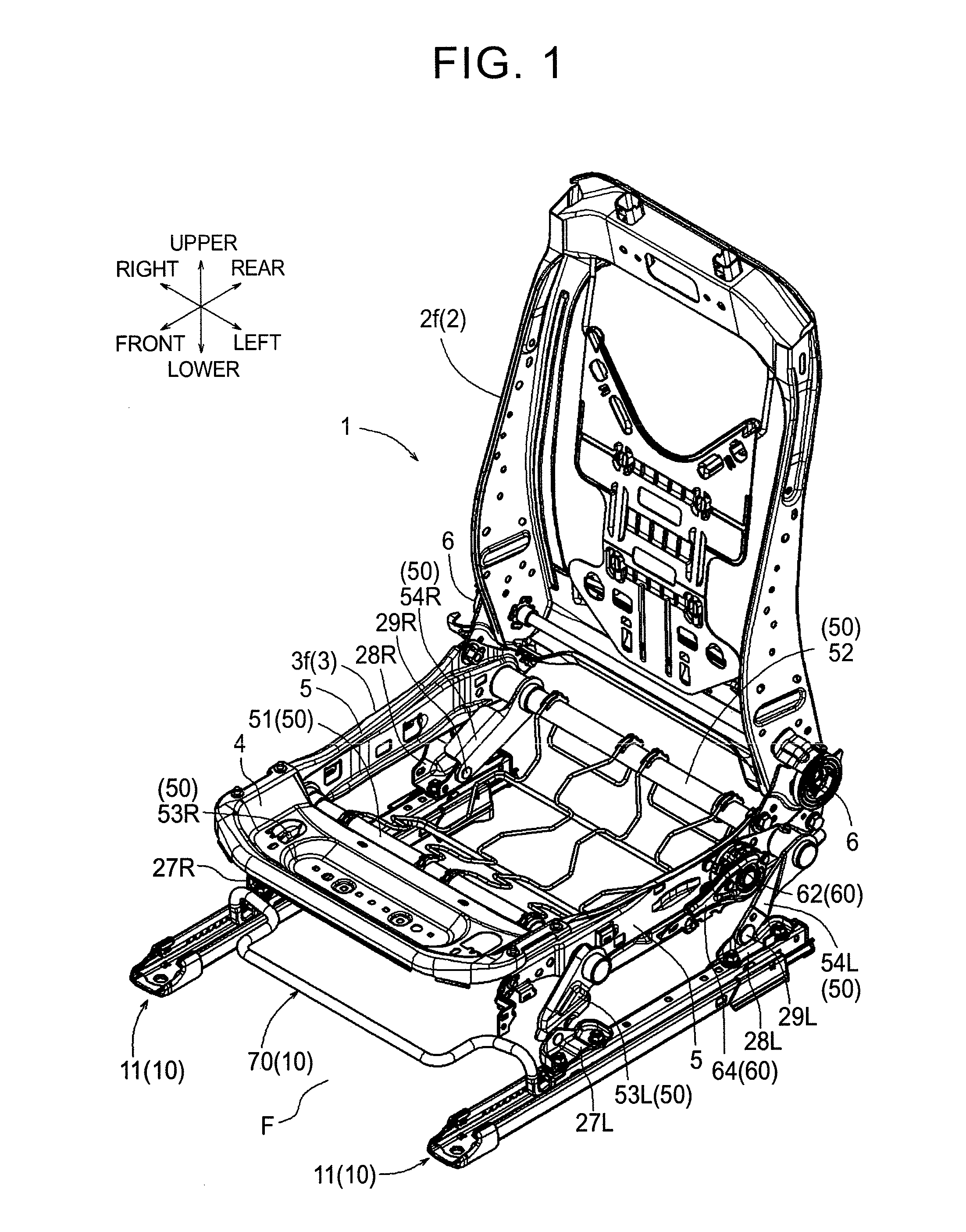
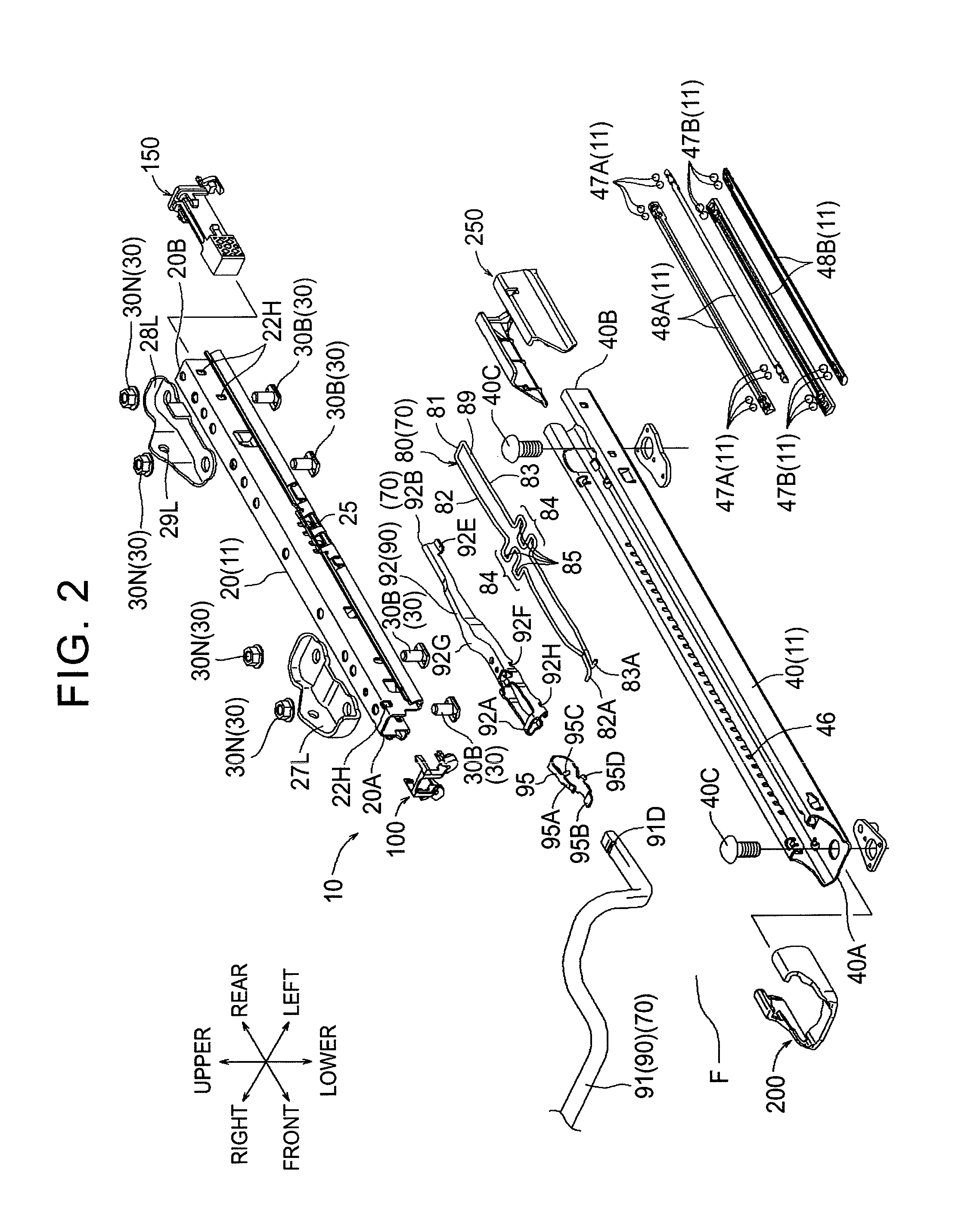
[0033]The following describes an embodiment of a vehicle seat of the present invention with reference to FIGS. 1 to 14. Note that the present embodiment deals with a front-side car seat among vehicle seats. Respective directions illustrated appropriately by arrows in each view correspond to a front side, a rear side, a top side, a bottom side, a right side, and a left side, when viewed from a sitting person sitting on a car seat employed in a vehicle and disposed toward a vehicle front side. Note that each view mainly illustrates an internal structure of a seat body so as to clearly describe a configuration of the embodiment. In view of this, in terms of a seatback 2 and a seat cushion 3, internal frame structures such as a back frame 2f and a cushion frame 3f forming a framework are mainly illustrated, and illustration and description on accessories such as an outer material and a seat pad put on an outer part of the seatback 2 and the seat cushion 3 may be omitted.
[0034]The car se...
PUM
 Abstract
Description
Claims
Application Information