Multi resonator non-adjacent coupling
- Summary
- Abstract
- Description
- Claims
- Application Information
AI Technical Summary
Benefits of technology
Problems solved by technology
Method used
Image

Examples
first embodiment
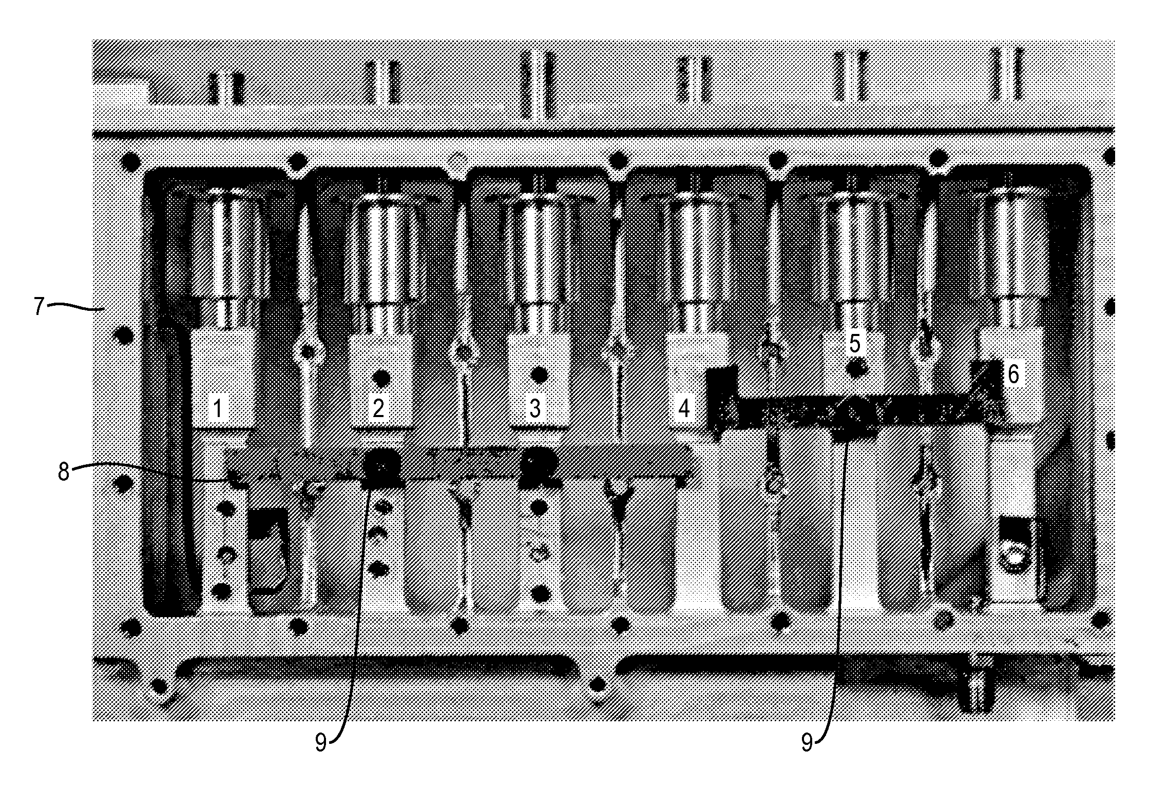
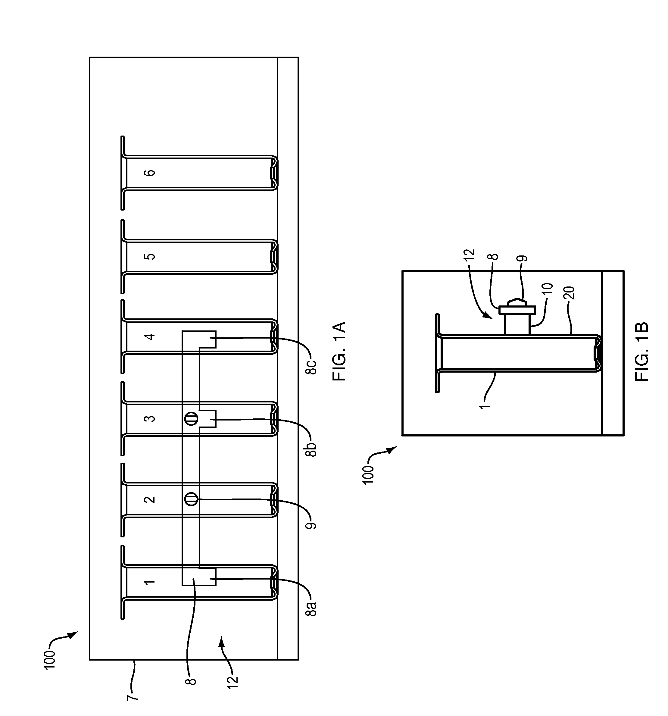
[0016]In reference to FIGS. 1A and 1B, a multi resonator filter 100 includes a set of six resonators, resonators 1-6, that are metal resonators with resonator cavities either forming part of resonator housing 7 or that are mechanically bolted or bonded to the housing 7. The housing 7 may be a metal housing. The filter 100 further includes a coupling 12 that is formed of a metal strip 8 and non-conductive (dielectric) spacers 10 fastened together with non-conductive (dielectric) screws 9. The spacers 10 space the metal strip 8 from a surface 20 of the resonators 2 and 3. That is, the configuration of coupling 12 couples resonators 1 and 4 and allows the jumping in doing so of resonators 2 and 3.
[0017]The present invention, works with any resonator configuration; however, it is more practical when the resonators are laid out horizontally, i.e., the resonators are accessible from the sides normally with a removable side cover of the housing 7.
[0018]Normally, a positive coupling between...
second embodiment
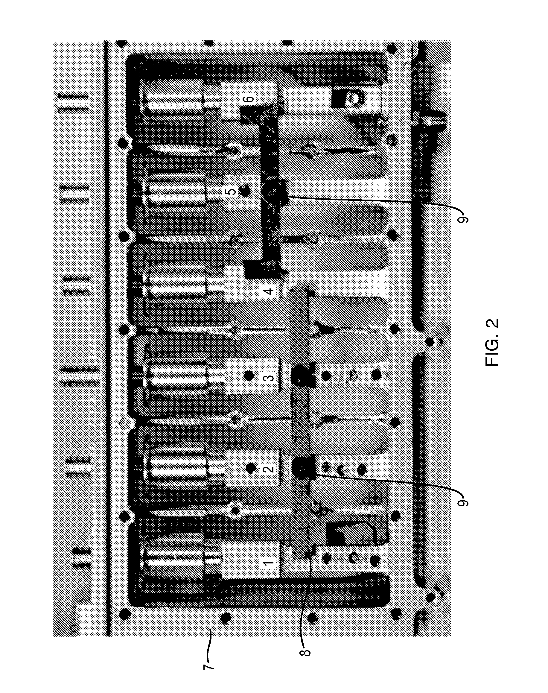
[0020]coupling 24 is shown in FIG. 2 for resonator filter 200. The resonator filter 20 includes the same six resonators 1-6 of FIGS. 1A and 1B. The coupling 24 also includes the coupling 12 of FIGS. 1A and 1B plus additional coupling element 26, which is a second metal strip coupling resonator 4 to resonator 6. For the geometry of the resonator filter 200 of FIG. 2, the measured coupling bandwidth values in frequency are:[0021]Resonators 1˜3=2.1 MHz[0022]Resonators 1˜4=3.3 MHz[0023]Resonators 2˜4=7.5 MHz
The coupling bandwidth values for couplings 1˜3 and 2˜4 are also controllable by adjusting the spacing, i.e., making a thickness of the spacer 10 thicker or thinner so as to adjust the gap between the metal strip 8 and the surface 20 of the resonator cavity.
[0024]Measured phase responses for the coupling bandwidths of Resonators 1-3, 1-4 and 2-4 using the coupling 12 of FIGS. 1A and 1B and the corresponding coupling element of coupling 24, are given in FIGS. 3-5. FIG. 6 shows the out...
PUM
 Abstract
Description
Claims
Application Information