High-voltage power source, charging device incorporating same, and high-voltage power supplying method

a charging device and high-voltage power technology, applied in the direction of instruments, electrographic process equipment, corona discharge, etc., can solve the problem of deteriorating image quality

Inactive Publication Date: 2015-04-02
RICOH KK
View PDF0 Cites 12 Cited by
  • Summary
  • Abstract
  • Description
  • Claims
  • Application Information

AI Technical Summary

Benefits of technology

[0007]Embodiments of the present invention described herein provide a high-voltage power source, a charging device incorporating the same, and a high-voltage power supplying method. The high-voltage power source includes a high-voltage power source unit configured to apply high voltage obtained by superposing a high alternating-current voltage on a high direct-current voltage to a charging member used to charge a photoreceptor of an image forming apparatus, an output unit configured to output a first direct-current voltage having a first voltage value according to an externally input pulse-width modulation signal, a direct-current voltage conversion unit configured to convert the first direct-current voltage into a second direct-current voltage, a generation unit configured to boost the second direct-current voltage to generate a high direct-current voltage, a peak value detection unit configured to detect a positive peak value and a negative peak value from an alternating-current component of the high direct-current voltage, and a voltage difference output unit configured to calculate a third voltage value by multiplying a difference between an absolute value of the positive peak value and an absolute value of the negative peak value by a coefficient α, and output a third direct-current voltage having the third voltage value to the direct-current voltage conversion unit. The coefficient α is a positive real number smaller than one. The direct-current voltage conversion unit outputs the second direct-current voltage having a voltage value calculated by subtracting the third voltage value from the first voltage value.

Problems solved by technology

Accordingly, the quality of the formed image deteriorates.

Method used


Image

  • High-voltage power source, charging device incorporating same, and high-voltage power supplying method
  • High-voltage power source, charging device incorporating same, and high-voltage power supplying method
  • High-voltage power source, charging device incorporating same, and high-voltage power supplying method

Examples


first embodiment

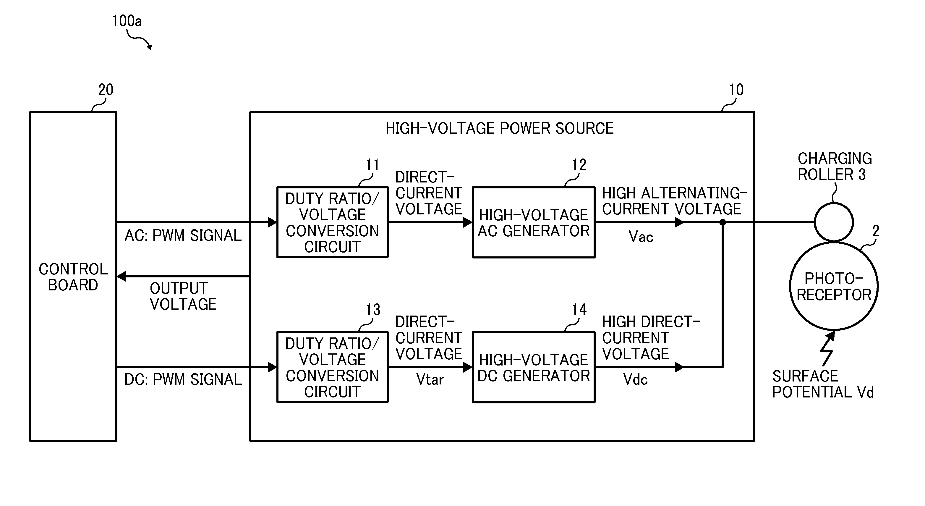
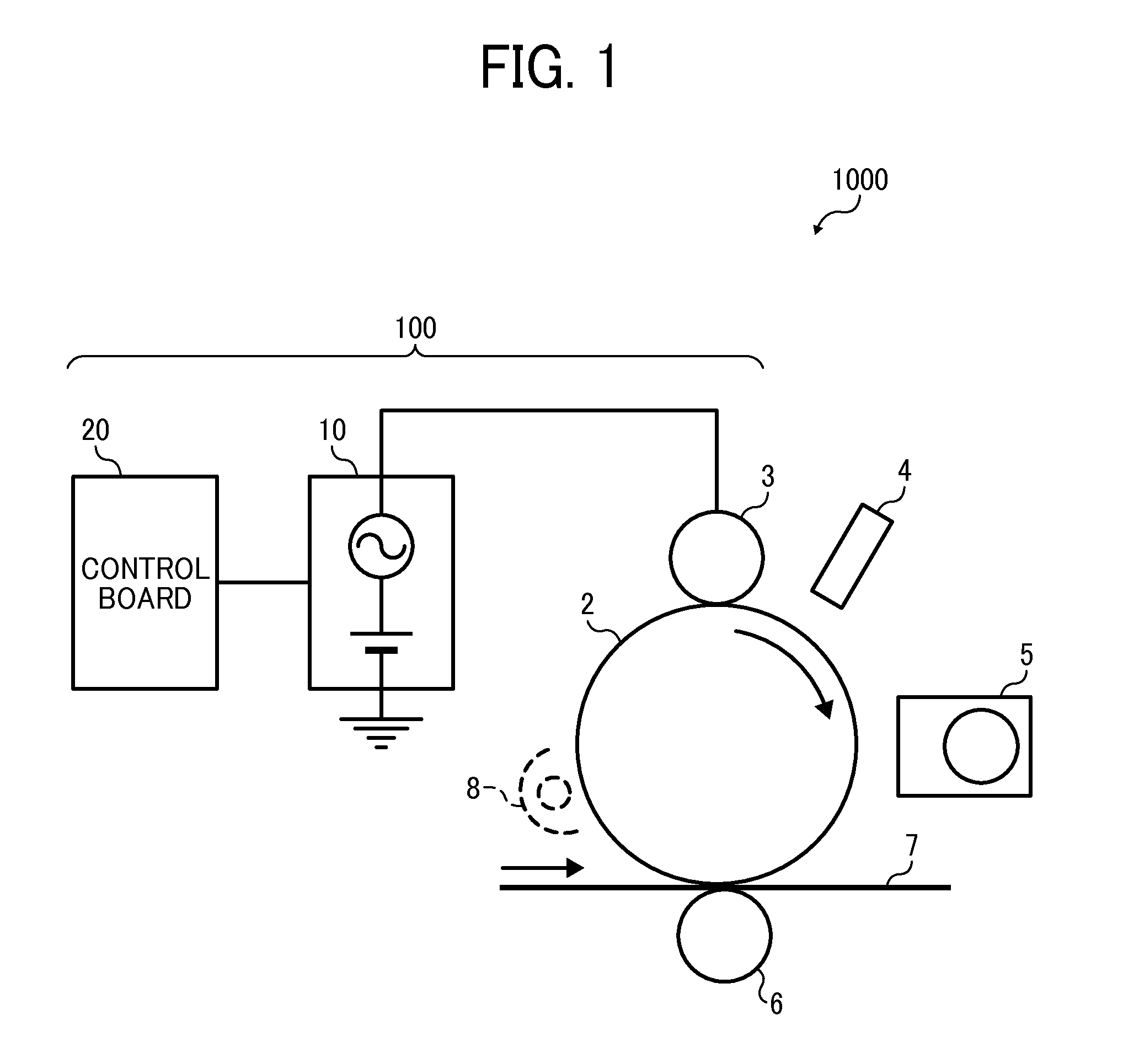
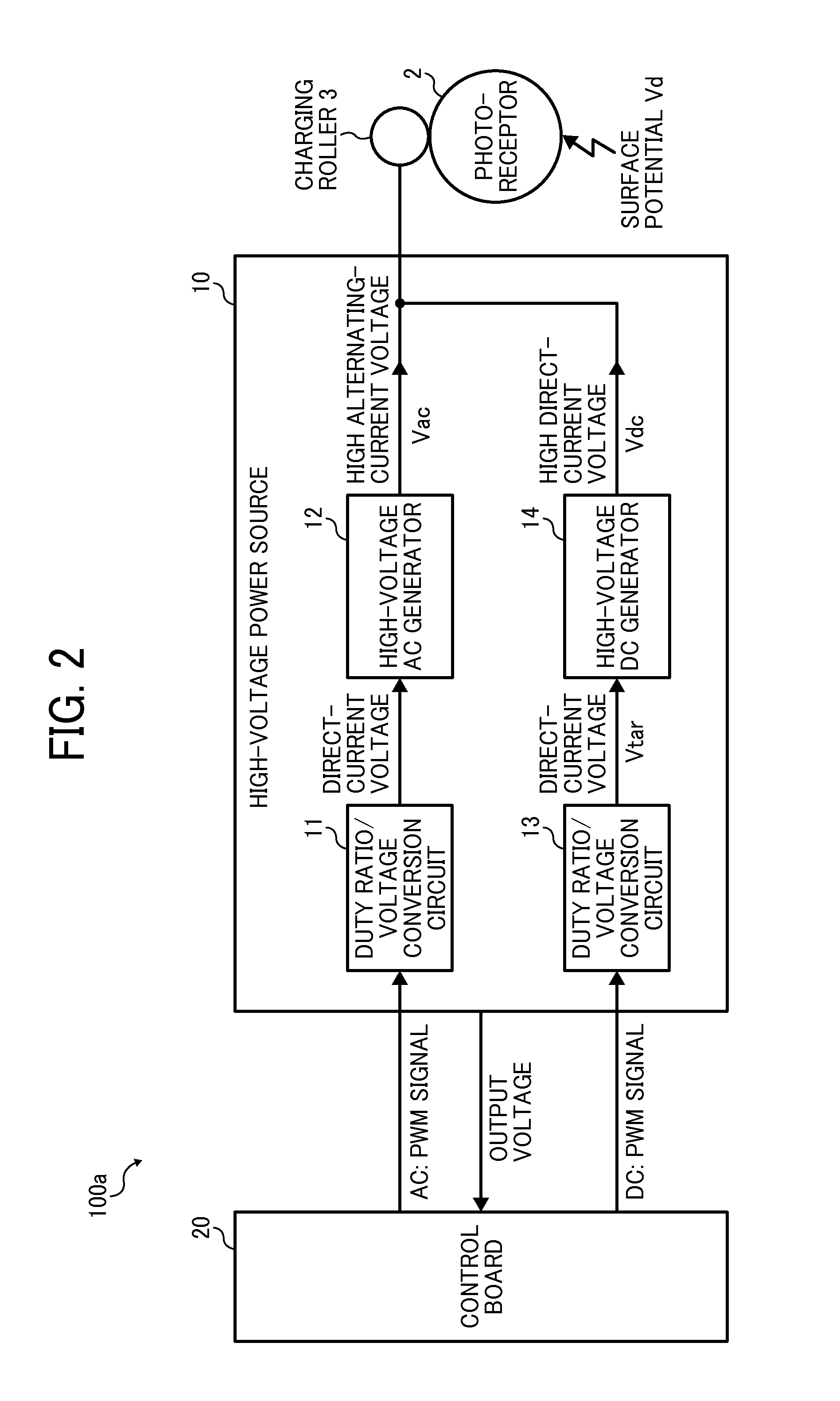
[0028]FIG. 1 is a schematic diagram illustrating the schematic configuration of an electrophotographic image forming apparatuses 1000 according to an example embodiment of the present invention. In FIG. 1, for the purpose of simplification, the image forming apparatuses 1000 includes only a high-voltage power source 10, a control board 20, a photoreceptor 2, a charging roller 3, an exposure device 4, a development device 5, a first transfer unit 6, and an intermediate transfer belt 7. The high-voltage power source 10, the control board 20, and the charging roller 3 together configure a charging device 100 according to the present example embodiment.

[0029]In the charging device 100 according to the present example embodiment, the high-voltage power source 10 generates high voltage by superposing a high direct-current voltage on a high alternating-current voltage, and applies the generated high voltage to the charging roller 3. As the photoreceptor 2 and the charging roller 3 are in c...

second embodiment

[0072]FIG. 9 is a block diagram illustrating the circuitry of a charging device 100b according to the second example embodiment of the present invention. In FIG. 9, like reference signs are given to elements similar to those of the charging device 100a according to the first example embodiment described above. In the following description, matters common to the first example embodiment are omitted where appropriate, and differences from the first example embodiment will mainly be described.

[0073]As illustrated in FIG. 9, a high-voltage power source 10b of the charging device 100b according to the present example embodiment includes a peak-value output control circuit 30 subsequent to the alternating-component peak detection circuit 17 of the first example embodiment. The peak-value output control circuit 30 includes sampling circuits 31 and 34, pulse-width modulation circuits 32 and 35 (A and B), and peak-value update circuits 33 and 36, subsequent to the positive peak detection cir...


PUM


Abstract

A high-voltage power source includes a high-voltage power source unit configured to apply high voltage obtained by superposing a high alternating-current voltage on a high direct-current voltage to a charging member, an output unit configured to output a first direct-current voltage having a first voltage value according to an externally input pulse-width modulation signal, a direct-current voltage conversion unit configured to convert the first direct-current voltage into a second direct-current voltage, a generation unit configured to boost the second direct-current voltage to generate a high direct-current voltage, a peak value detection unit configured to detect a positive peak value and a negative peak value from an alternating-current component of the high direct-current voltage, and a voltage difference output unit configured to output a third direct-current voltage having a third voltage value to the direct-current voltage conversion unit.

Description

CROSS-REFERENCE TO RELATED APPLICATIONS[0001]This patent application is based on and claims priority pursuant to 35 U.S.C. §119(a) to Japanese Patent Application Nos. 2013-206131 and 2014-048455, filed on Oct. 1, 2013, and Mar. 12, 2014, respectively, in the Japan Patent Office, the entire disclosure of which is hereby incorporated by reference herein.BACKGROUND[0002]1. Technical Field[0003]Example embodiments of the present invention generally relate to a high-voltage power source, a charging device incorporating that high-voltage power source, and a high-voltage power supplying method.[0004]2. Background Art[0005]In electrophotographic image forming apparatuses, the surface of a photoreceptor needs to be charged so as to have a desired electrical potential, for the formation of an image of good quality. In this respect, a method of applying high voltage to a charging roller that charges a photoreceptor is known. In this method, the high voltage applied to the charging roller is a ...

Claims


Application Information

Patent Timeline
Patent Type & Authority Applications(United States)
IPC IPC(8): G03G15/00G03G15/02
CPCG03G15/0266G03G15/80
Inventor MINAMI, SHINJI
Owner RICOH KK
Why Eureka
Try Eureka