
Nanoelectromechanical bistable cantilever device

Inactive Publication Date: 2009-11-03
NORTHWESTERN UNIV
View PDF15 Cites 56 Cited by
  • Summary
  • Abstract
  • Description
  • Claims
  • Application Information

AI Technical Summary

Benefits of technology

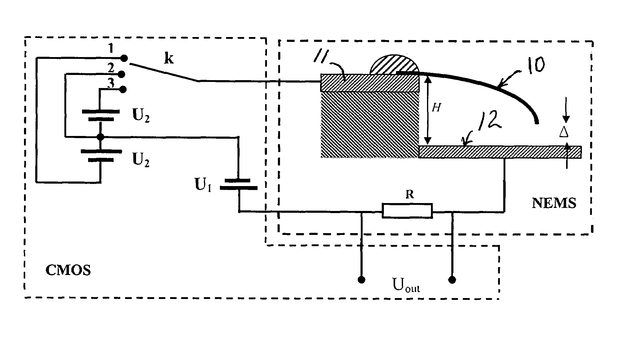
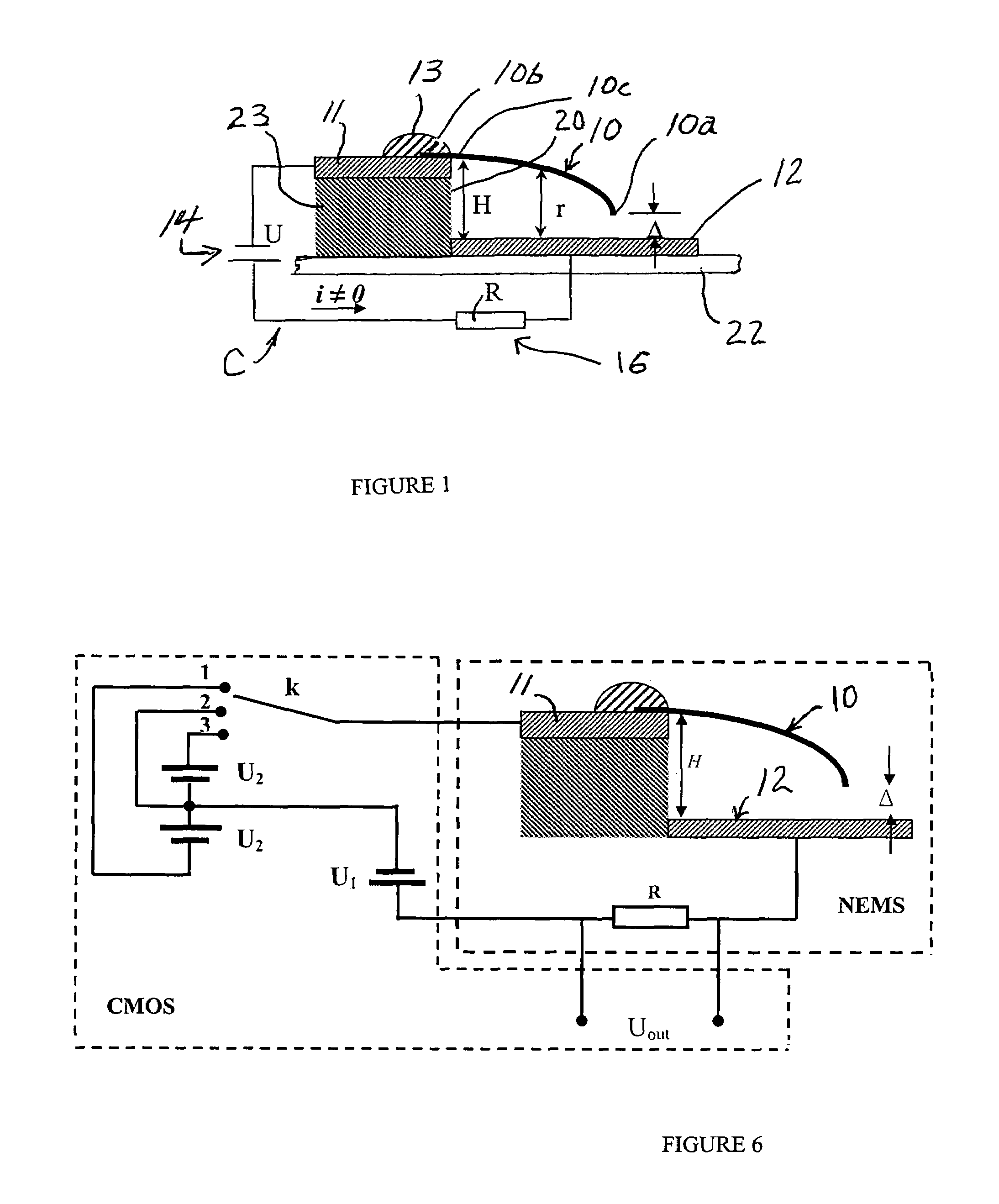
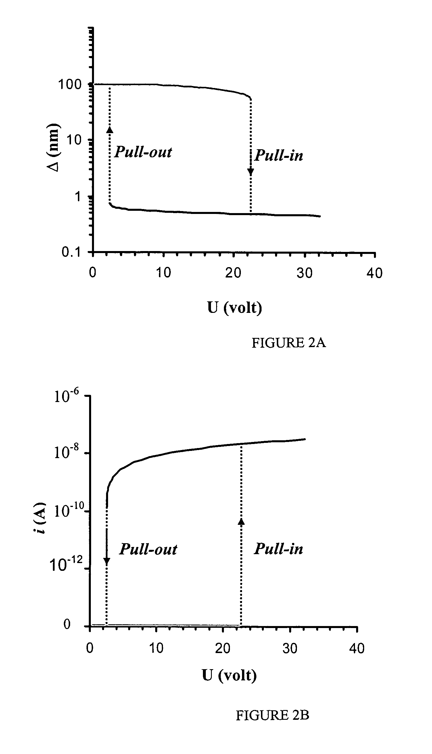
[0007]The present invention provides in an embodiment a nanoelectromechanical device having features to provide two stable cantilever positions and a hysteresis loop in the current-voltage space between a pull-in voltage and a pull-out voltage. The nanoelectromechanical device comprises an electrically conductive or semiconducting nano-cantilever wherein the nano-cantilever has a free end that is movable relative to an electrically conductive substrate such as an electrode of a circuit. The circuit includes a power source connected to the substrate and to the nano-cantilever for providing a pull-in

Problems solved by technology

A hysteretic response results.

Method used


Image

  • Nanoelectromechanical bistable cantilever device
  • Nanoelectromechanical bistable cantilever device
  • Nanoelectromechanical bistable cantilever device

Examples


Embodiment Construction

[0021]Referring to FIG. 1, a nano-electromechanical device is schematically shown for purposes of illustrating the invention and not limiting it. For example, the nano-electromechanical device is shown including a nano-cantilever 10 comprising electrically conductive or semiconducting material wherein the nano-cantilever has a free end or tip 10a that is movable relative to an electrically conductive substrate shown as an electrode 12 of a circuit C. The nano-cantilever also includes a fixed end 10b fixedly attached by electrically conductive attachment material 13 to an electrically conductive substrate shown as an electrical lead or contact 11 of the circuit C. The material 13 can comprise a metallic material deposited on the fixed end 10b in such a manner as to metallurgically attach the fixed end to the lead or contact 11. For purposes of illustration and not limitation, the attachment material 13 can comprise a metal or alloy, such as platinum (Pt) and tungsten (W), electron be...


PUM


Abstract

Nano-electromechanical device having an electrically conductive nano-cantilever wherein the nano-cantilever has a free end that is movable relative to an electrically conductive substrate such as an electrode of a circuit. The circuit includes a power source connected to the electrode and to the nano-cantilever for providing a pull-in or pull-out voltage therebetween to effect bending movement of the nano-cantilever relative to the electrode. Feedback control is provided for varying the voltage between the electrode and the nano-cantilever in response to the position of the cantilever relative to the electrode. The device provides two stable positions of the nano-cantilever and a hysteresis loop in the current-voltage space between the pull-in voltage and the pull-out voltage. A first stable position of the nano-cantilever is provided at sub-nanometer gap between the free end of the nano-cantilever and the electrode with a pull-in voltage applied and with a stable tunneling electrical current present in the circuit. A second stable position of the nano-cantilever is provided with a pull-out voltage between the cantilever and the electrode with little or no tunneling electrical current present in the circuit. The nano-electromechanical device can be used in a scanning probe microscope, ultrasonic wave detection sensor, NEMS switch, random access memory element, gap sensor, logic device, and a bio-sensor when the nano-cantilever is functionalized with biomolecules that interact with species present in the ambient environment be them in air or aqueous solutions. In the latest case, the NEMS needs to be integrated with a microfluidic system.

Description

[0001]This application claims priority and benefits of provisional application Ser. No. 60 / 701,586 filed Jul. 22, 2005.CONTRACTUAL ORIGIN OF THE INVENTION[0002]This invention was supported by funding under National Science Foundation Grant / Contract No. CMS-0120866 and Federal Aviation Association Grant / Contract No. DTFA03-01-C-0031. The Government may have certain rights in the invention.FIELD OF THE INVENTION[0003]The present invention relates to an electromechanical device having a nano-cantilever movable relative to an electrode and feedback control in a manner to provide two stable cantilever positions and a hystersis loop in the current-voltage space between a pull-in voltage and a pull-out voltage as well as to a method of its manufacture and use.BACKGROUND OF THE INVENTION[0004]Nanoelectromechanical systems (NEMS) are attracting significant attention because of their properties to enable superior electronic components and sensors. By exploiting nanoscale effects, NEMS present...

Claims


Application Information

Patent Timeline
IPC IPC(8): H01L29/84H01L31/109
CPCB81B3/0054G11B9/1445G11C13/025G11C23/00H01H1/0094B82Y10/00B81B2201/038B81B2201/07B81B2201/12B81B2203/0118H01H59/0009B82Y15/00
Inventor ESPINOSA, HORACIO D.KE, CHANGHONG
Owner NORTHWESTERN UNIV
Learn More