Protective mat with bottom surface having enhanced coefficient of friction

a protective mat and bottom surface technology, applied in the field of protective mats, can solve the problems of mats without protrusions that do not interact sufficiently with hard flooring to prevent mat movement, lack of penetration of protrusions, and poor performance of mats with carpeted flooring. , to achieve the effect of reducing the chance of slipping, reducing body thickness, and reducing the chance of deflection

Inactive Publication Date: 2015-04-02
ROBBINS EDWARD S III
View PDF3 Cites 4 Cited by
  • Summary
  • Abstract
  • Description
  • Claims
  • Application Information

AI Technical Summary

Benefits of technology

[0007]A single unitary mat is provided for use on an underlying surface including a carpeted surface, a hard floor surface, or both. The mat can have a substantially planar upper surface suitable for walking traffic and for interaction with a chair support structure that typically includes a plurality of wheels or casters on the lower outside points of a spider. The mat upper surface can include small variations that reduce the chance for slipping. The mat can include a body, typically made of polyvinyl chloride (PVC), polypropylene, high density polyethylene, polyester copolymers, or polycarbonate, of a variety of thicknesses. When the mat is to be used in an office situation to support a wheeled chair, the thickness of the body can be sufficient to exhibit very little deflection at the points supporting the chair. When the mat is to be used in a high pedestrian traffic area, th

Problems solved by technology

Floor mats and chair mats can include an array of short point-like protrusions on an underside surface of the mat, that are intended to hold the mat firmly in place on carpet, but such protrusions do not interact sufficiently with hard flooring to prev

Method used


Image

  • Protective mat with bottom surface having enhanced coefficient of friction
  • Protective mat with bottom surface having enhanced coefficient of friction
  • Protective mat with bottom surface having enhanced coefficient of friction

Examples


Embodiment Construction

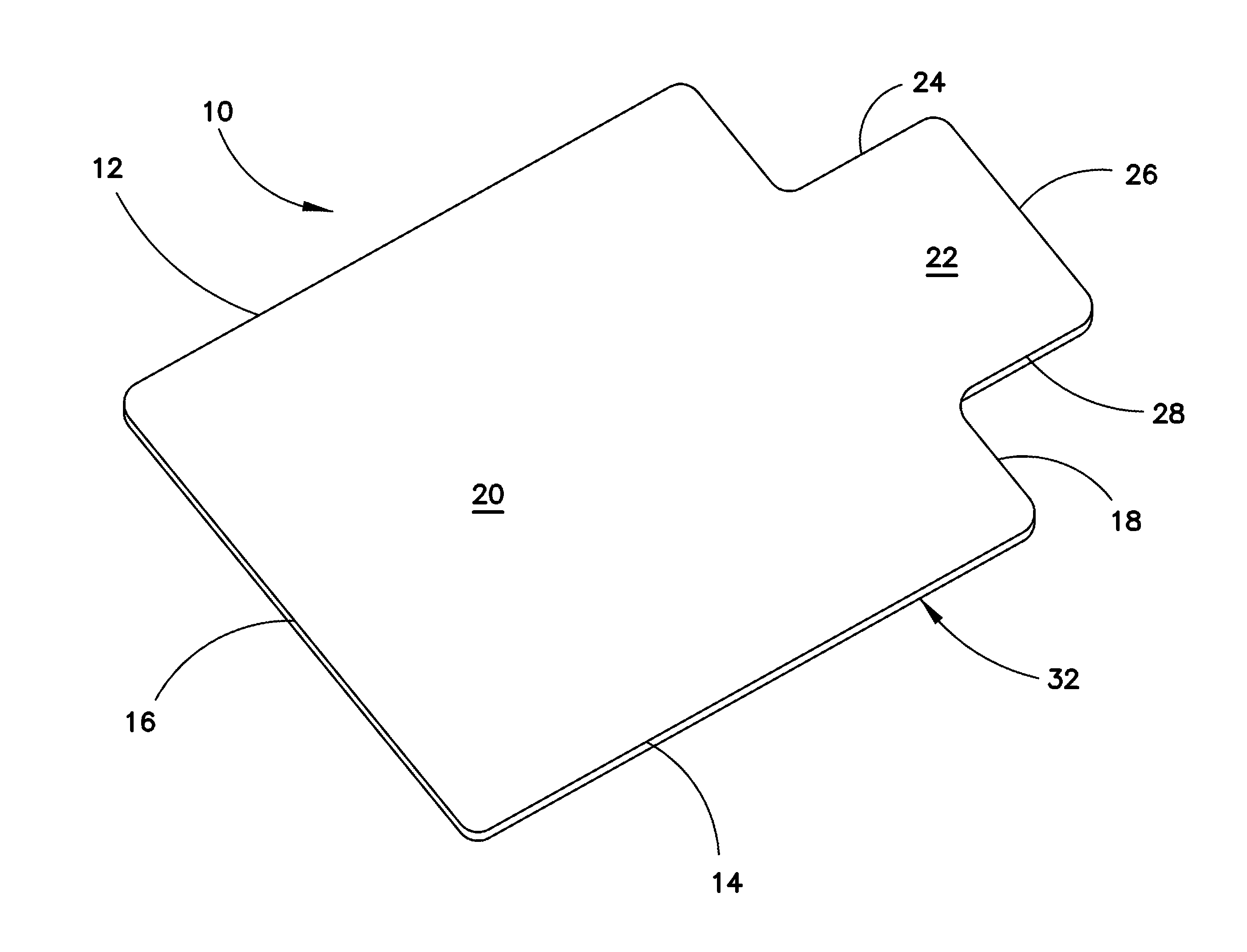
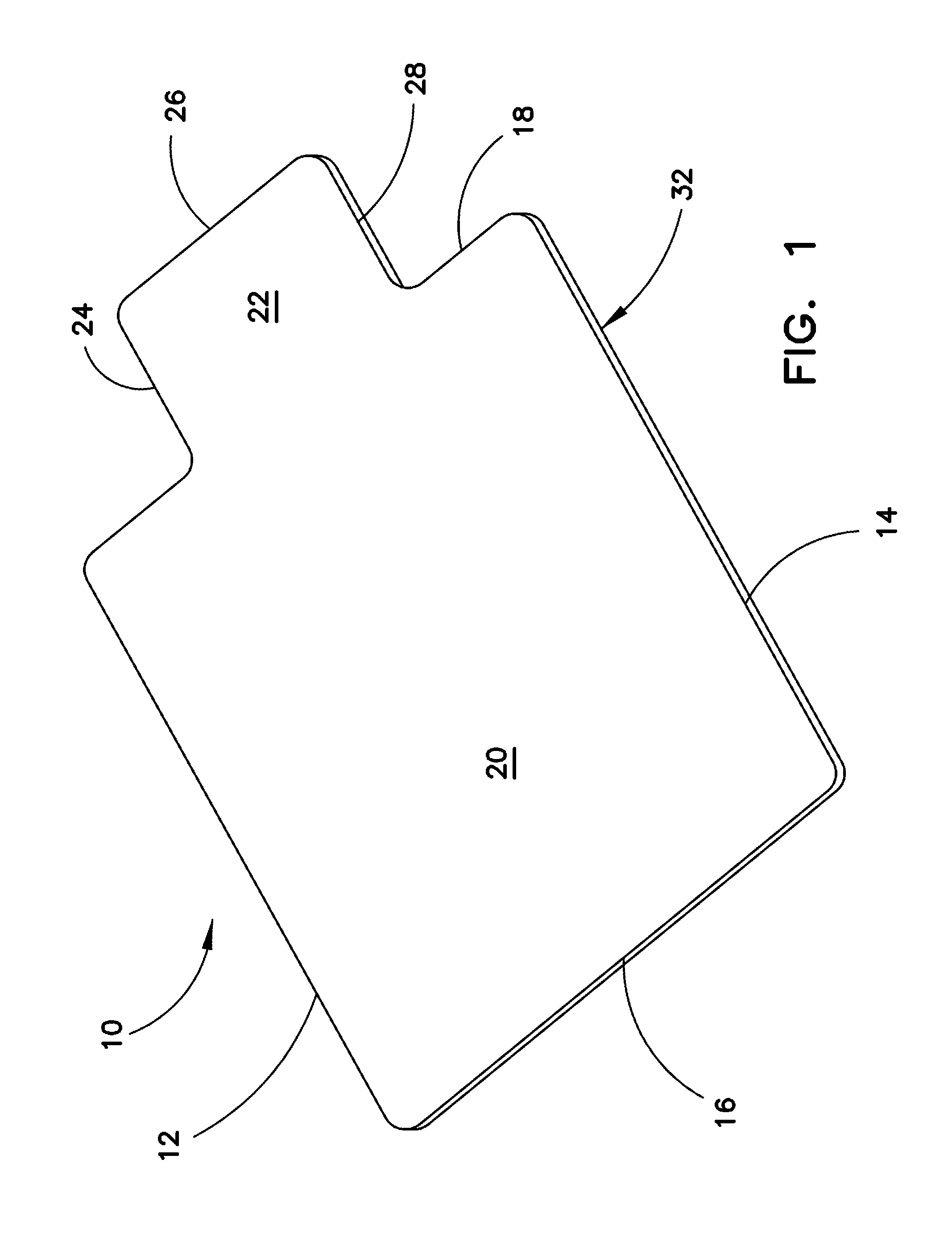
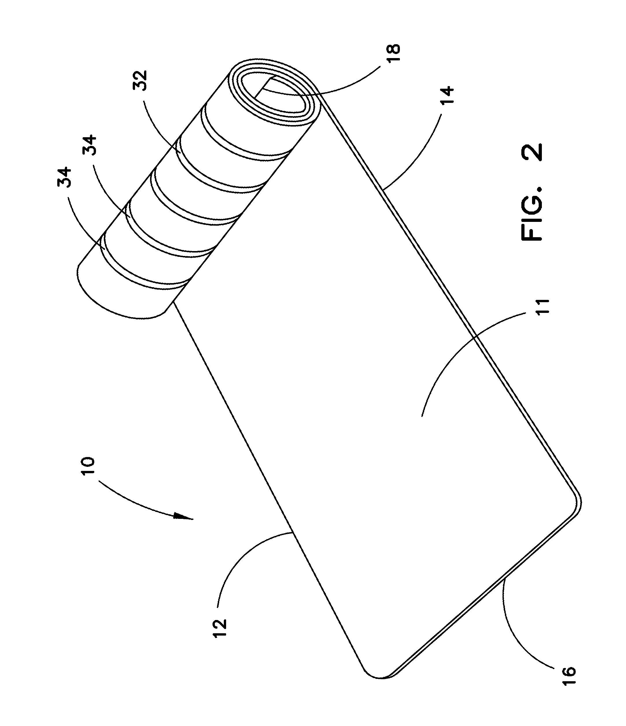
[0013]Referring to the drawings, wherein like reference numerals refer to like components, there is shown in FIG. 1 an embodiment of a mat 10 for use on a variety of flooring surfaces. The mat 10 can be formed of a planar, semi-rigid member body 11 having a first side and a second side opposite the first side. The mat 10 may also include four side edges 12, 14, 16 and 18, which define a major portion, or first portion, 20 of the mat 10. An optional extension portion 22 that can be of the same material and thickness as the major portion 20, can project or extend integrally from the side edge 18. The optional portion 22, can be further defined by edges 24, 26, 28, which complete the periphery 30 of the mat 10. The extension 22 is designed to project into the well area of a desk or other work surface, with the remainder of the mat 10 positioned behind the desk and serving as the principal contact area for a chair, such as a desk chair, typically (but not necessarily) fitted with roller...


PUM

PropertyMeasurementUnit
Lengthaaaaaaaaaa
Thicknessaaaaaaaaaa
Electrical resistanceaaaaaaaaaa

Abstract

A mat is provided for use on a carpeted floor surface, a hard floor surface, or both, and can have a substantially planar upper body surface suitable for interaction with a chair or other support structure. A slip-resistant layer can be bonded to a substantially planar lower body surface of the mat. The slip-resistant layer can be in the form of strips or coextensive with the entire lower body surface. The slip-resistant layer can allow placement in applications requiring simultaneous placement on both carpeted and hard floor surfaces, yet facilitating stable placement on both surfaces.

Description

PRIORITY[0001]This application claims the benefit of priority of U.S. Provisional Patent Application No. 61 / 884,329, filed Sep. 30, 2013, which is incorporated herein by reference in its entirety.BACKGROUND[0002]1. Field of the Invention[0003]This invention generally relates to protective mats, and particularly to chair and floor mats used in the office and home to cover selected areas of carpeting and / or bare flooring having an anti-slippage means.[0004]2. Background of the Invention[0005]Floor mats and chair mats, for office and home use are well known and typically used on hard flooring and / or carpeted flooring. Floor mats are often used in high traffic areas to protect the underlying flooring. Likewise chair mats are typically used to reduce the impact and wear that can be caused by the chair rollers on the supporting chair spider. With both floor mats and chair mats it is desirable that any movement between the mat and the underlying flooring caused by the activity occurring on...

Claims


Application Information

Patent Timeline
IPC IPC(8): B32B27/08B32B3/08
CPCB32B27/08B32B3/085B32B2250/02B32B2307/744B32B2475/00B32B2331/04B32B2398/20B32B2471/04B32B2375/00B32B27/304B32B27/306B32B27/36B32B27/365B32B27/40B32B3/266B29C48/07B29C48/08B29C48/21Y10T428/24752Y10T428/24802Y10T428/2495Y10T428/26Y10T428/269
Inventor ROBBINS, III, EDWARD S.BAIN, JR., MILTON F.
Owner ROBBINS EDWARD S III
Why Eureka
Try Eureka