Computational design method and interface

a design method and interface technology, applied in the field of drawing programs, can solve problems such as the inability to attach code directly to geometry

Active Publication Date: 2015-04-02
AUTODESK INC
View PDF7 Cites 9 Cited by
  • Summary
  • Abstract
  • Description
  • Claims
  • Application Information

AI Technical Summary

Benefits of technology

[0007]Embodiments of the invention (referred to as ‘Project Honeycomb’) allow users to supercharge aspects of parametric modeling applications (e.g., Autodesk™ Vasari™ or Revit™) by embedding code and logic into content called families (similar to blocks [e.g., in Autocad™] or parts [e.g., in Inventor™]). It allows end-users to write a small program (via a scripting la...

Problems solved by technology

There exist methods for generating geometry with code or script,...

Method used


Image

  • Computational design method and interface
  • Computational design method and interface
  • Computational design method and interface

Examples


embodiments details

Software Embodiments Details

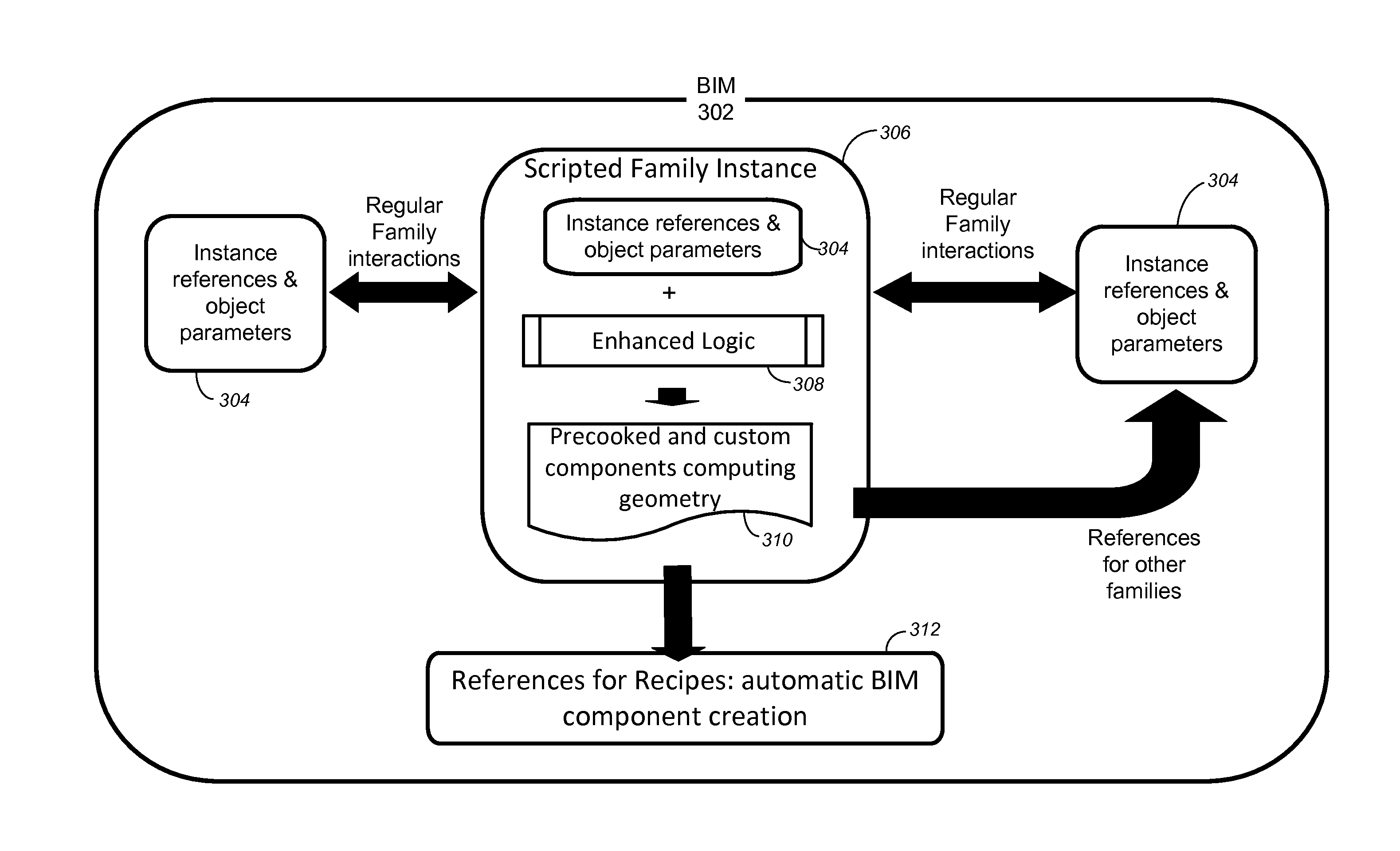
[0040]Parametric modeling applications such as business information models (BIM) exist in the prior art. As used herein, a parametric modeler refers to a finite-dimensional model that can be described using a finite number of parameters. Further, a parametric modeler is aware of the characteristics of components and the interactions between them. In other words, a parametric modeler maintains consistent relationships between elements as a model is manipulated. For example, in a parametric building modeler, if the pitch of the roof is changed, the walls automatically follow the revised roof line. In parametric modeling applications, a user may create a large project (e.g., a building) as well as smaller pieces of the building (e.g., windows, doors, chairs, roof, etc.). The smaller pieces referred to as sub-objects also have a parametric representation (i.e., can be presented using a parametric equation based on one or more parameters). In a parametric mode...


PUM


Abstract

A method, system, apparatus, computer program product, and computer readable storage medium provide the ability to define an object in a parametric modeling application. Geometric parametric objects are authored and organized into a family definition. Via a user interface, enhanced computational logic is defined. The logic is compiled into the family definition such that the enhanced computational logic is embedded at an object level of the one or more geometric parametric objects. Upon a building information model requiring a regeneration operation, the compiled enhanced computational logic is automatically executed.

Description

CROSS-REFERENCE TO RELATED APPLICATIONS[0001]This application claims the benefit under 35 U.S.C. Section 119(e) of the following co-pending and commonly-assigned U.S. provisional patent application(s), which is / are incorporated by reference herein:[0002]Provisional Application Ser. No. 61 / 883,766, filed on Sep. 27, 2013, by Matthew David Jezyk, Lev Lipkin, Stephen Elliott, and Peter Benjamin Boyer, entitled “COMPUTATIONAL DESIGN METHOD AND INTERFACE,” attorneys' docket number 30566.511-US-P1.BACKGROUND OF THE INVENTION[0003]1. Field of the Invention[0004]The present invention relates generally to drawing programs, and in particular, to a method, apparatus, and article of manufacture for attaching code directly to the geometry in a drawing.[0005]2. Description of the Related Art[0006]There exist methods for generating geometry with code or script, but there is currently not a way to attach code directly to geometry. Embodiments of the invention aim to solve that problem.SUMMARY OF TH...

Claims


Application Information

Patent Timeline
IPC IPC(8): G06F9/44G06F9/45
CPCG06F8/34G06F8/313G06F8/41
Inventor JEZYK, MATTHEW DAVIDLIPKIN, LEVELLIOTT, STEPHEN J.BOYER, PETER BENJAMIN
Owner AUTODESK INC
Why Eureka
Try Eureka