Reconfigurable memristor-based computing logic

a computing logic and reconfiguration technology, applied in the field of electronic circuit design, can solve the problems of not being scalable, not being able to reconfigure logic types, not being able to scale,

Inactive Publication Date: 2013-04-23
THE UNITED STATES OF AMERICA AS REPRESETNED BY THE SEC OF THE AIR FORCE
View PDF5 Cites 13 Cited by
  • Summary
  • Abstract
  • Description
  • Claims
  • Application Information

AI Technical Summary

Benefits of technology

[0014]It is an object of the present invention to provide an apparatus for computing logic that can be electrically reconfigured to perform any one of several boolean operations.
[0015]It is another object of the present invention, then, to provide an apparatus for electrically reconfigurable computing logic that employs fundamental building block structure for a high order of scalability.
[0016]It is yet another object of the present invention to provide an apparatus for electrically reconfigurable computing logic that will maintain its reconfigured state in the absence of supply power or power consumption.

Problems solved by technology

Today, this type of logic reconfiguration is not possible as the operational functionality of transistors, resistors, capacitors, and inductors is fixed and electronically unchangeable.
This method has the disadvantage, however, in that it is not scalable, it relies upon software to reconfigure the logic functions and it requires external memory because the memory element in its FPGA is volatile.
This method has the disadvantage, however, in that it does not scale.
This method has the disadvantage, however, in that it does not scale and it requires software to reconfigure logic functions.
This method also has the disadvantage in that it does not scale.
This method has the disadvantage, however, in that it uses current mirror circuits which continuously consume current, rendering this method not scalable, and it requires software to choose the optimal memristance value.
This method has the disadvantage, however, in that it does not scale; it requires software to reconfigure the logic functions and the reconfiguration of the logic function is not optimal in that the selection of a logic function is based on the path taken from the wiring of the logic gates.
What is lacking in the prior art, therefore, is computing logic circuitry that is capable of being electronically reconfigured to perform various Boolean functions in a scalable fashion and that will retain its reconfigured state in the absence of applied current or voltage.

Method used


Image

  • Reconfigurable memristor-based computing logic
  • Reconfigurable memristor-based computing logic
  • Reconfigurable memristor-based computing logic

Examples


Embodiment Construction

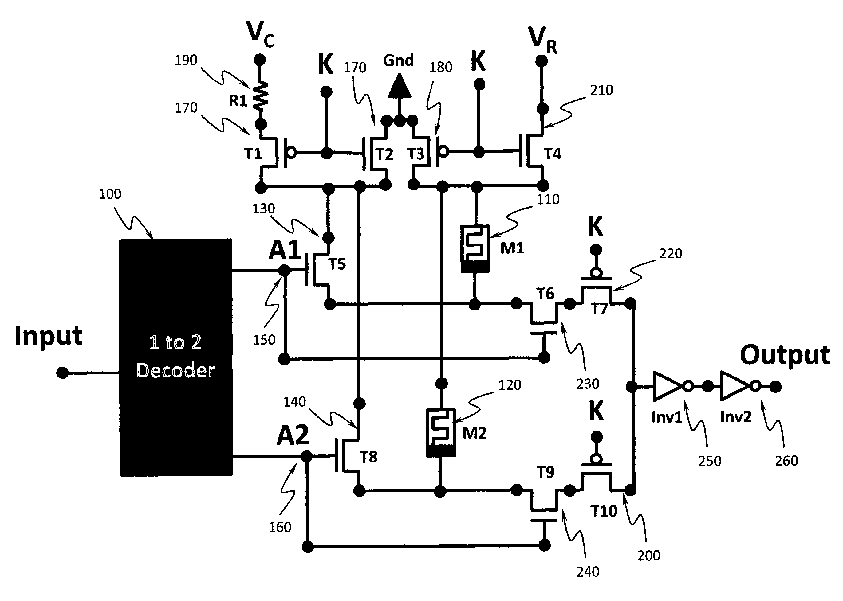
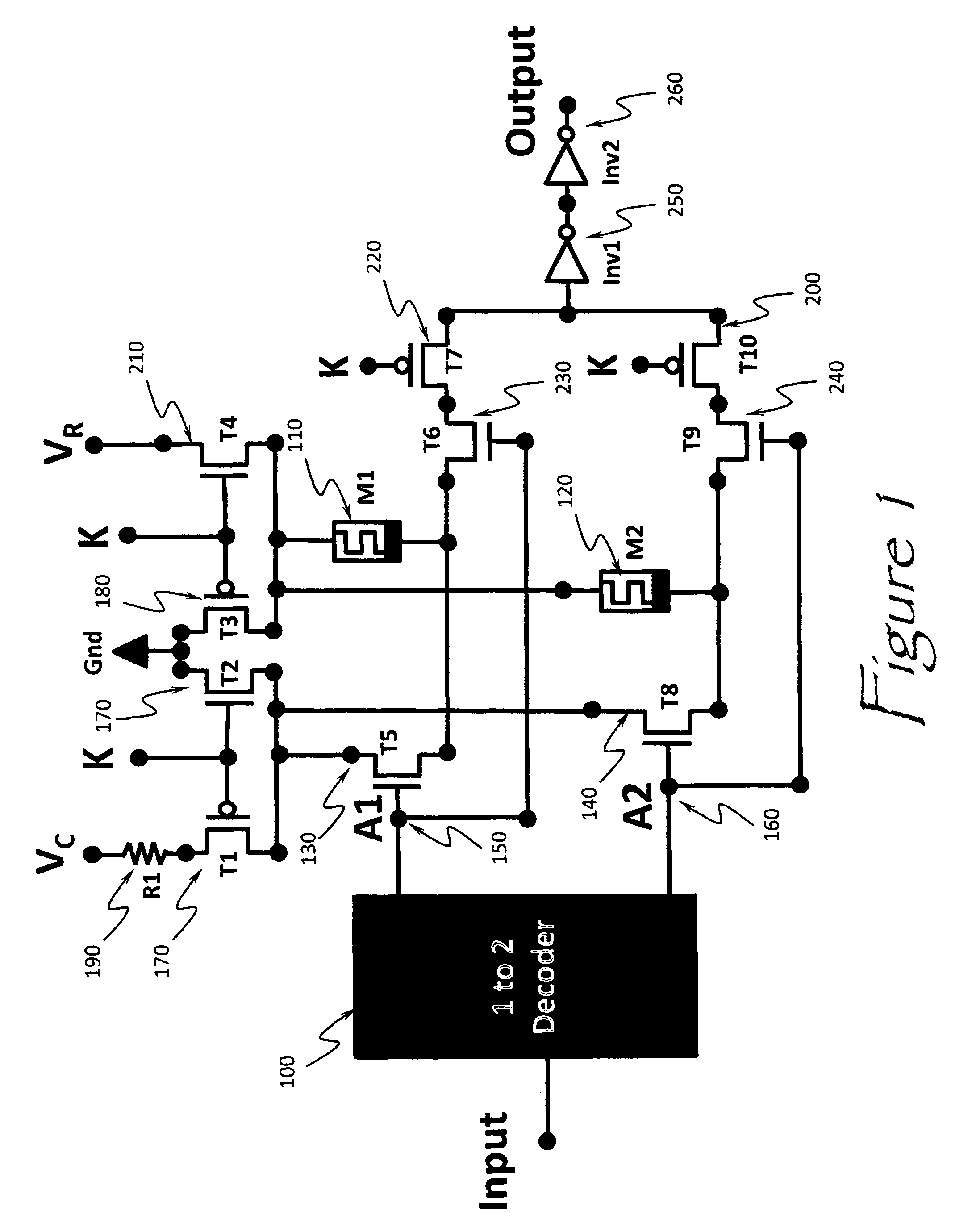
[0037]The present invention provides an apparatus and method for implementing a reconfigurable computing logic circuit based upon the reprogrammable properties of memristors.

[0038]The present invention comprises of several key features. Referring to FIG. 1 depicts a basic embodiment of the present invention. A digital binary decoder 100 is used to take multiple inputs and select a single output out of multiple combinations. A binary decoder which has an n-bit binary input code and a one activated output out-of-2n output code is called a binary decoder, and it is used when it is necessary to activate exactly one of its 2n outputs based on an n-bit input value [6]. The remaining elements of the present invention's computing architecture design components generally comprise n- and p-channel field effect transistors, resistors, and inverting logic gates in various quantities and configurations.

[0039]Still referring to FIG. 1, describes one basic embodiment of the present invention compr...


PUM


Abstract

An apparatus for reconfigurable computing logic implemented by an innovative memristor based computing architecture. The invention employs a decoder to select memristor devices whose ON / OFF impedance state will determine the reconfigurable logic output. Thus, the resulting circuit design can be electronically configured and re-configured to implement any multi-input / output Boolean logic computing functionality. Moreover, the invention retains its configured logic state without the application of a current or voltage source.

Description

PRIORITY CLAIM UNDER 35 U.S.C. §119(e)[0001]This patent application claims the priority benefit of the filing date of a provisional application Ser. No. 61 / 463,957, filed in the United States Patent and Trademark Office on Feb. 25, 2011.STATEMENT OF GOVERNMENT INTEREST[0002]The invention described herein may be manufactured and used by or for the Government for governmental purposes without the payment of any royalty thereon.BACKGROUND OF THE INVENTION[0003]This invention relates generally to the field of electronic circuit design. More specifically, this invention relates to electronic circuits which have a reprogrammable function. More specifically still, the present invention relates to reprogrammable electronic circuits which can function as reconfigurable logic circuits.[0004]Reconfigurable computing logic describes the ability to transform the functionally of a Boolean function from let us say a logic AND gate to a logic OR gate functionality without physical rewiring and vice...

Claims


Application Information

Patent Timeline
Patent Type & Authority Patents(United States)
IPC IPC(8): H03K19/173
CPCG11C13/0007H03K19/173
Inventor PINO, ROBINSON E.PINO, YOUNGOK K.
Owner THE UNITED STATES OF AMERICA AS REPRESETNED BY THE SEC OF THE AIR FORCE
Why Eureka
Try Eureka