Swing wing tip system, assembly and method with dual load path structure

a technology of wing tip and assembly method, which is applied in the direction of airflow influencers, wing adjustment, aircraft stabilisation, etc., can solve the problems of limiting or preventing the use of aircraft, affecting the use of later generations of aircraft, and modifying or reconfiguring airport infrastructure, such as gates, taxiways, runways, etc., to achieve the effect of improving the wing tip system, assembly and method

Active Publication Date: 2015-04-09
THE BOEING CO
View PDF49 Cites 38 Cited by
  • Summary
  • Abstract
  • Description
  • Claims
  • Application Information

AI Technical Summary

Benefits of technology

[0010]This need for an improved wing tip system, assembly, and method is satisfied. As discussed in the below detailed description, embodiments of the improved wing tip system, assembly, and method may provide significant advantages over known wing tip systems, assemblies, and methods.

Problems solved by technology

However, increasing or lengthening the wingspan of an aircraft to increase aircraft performance may limit or prevent the aircraft's use at airports having size restrictions with respect to airport gates, taxiways, runways, or other infrastructure.
Airports with airport gates, taxiways, runways, and other infrastructure constructed for one generation of aircraft may be too small to accommodate later generations of aircraft having increased wingspans.
However, modifying or reconfiguring such airport infrastructure, including gates, taxiways, and runways, may be an expensive and time consuming undertaking.
However, such known wing structures may only have a single load path.

Method used


Image

  • Swing wing tip system, assembly and method with dual load path structure
  • Swing wing tip system, assembly and method with dual load path structure
  • Swing wing tip system, assembly and method with dual load path structure

Examples


Embodiment Construction

[0045]Disclosed embodiments will now be described more fully hereinafter with reference to the accompanying drawings, in which some, but not all of the disclosed embodiments are shown. Indeed, several different embodiments may be provided and should not be construed as limited to the embodiments set forth herein. Rather, these embodiments are provided so that this disclosure will be thorough and complete and will fully convey the scope of the disclosure to those skilled in the art.

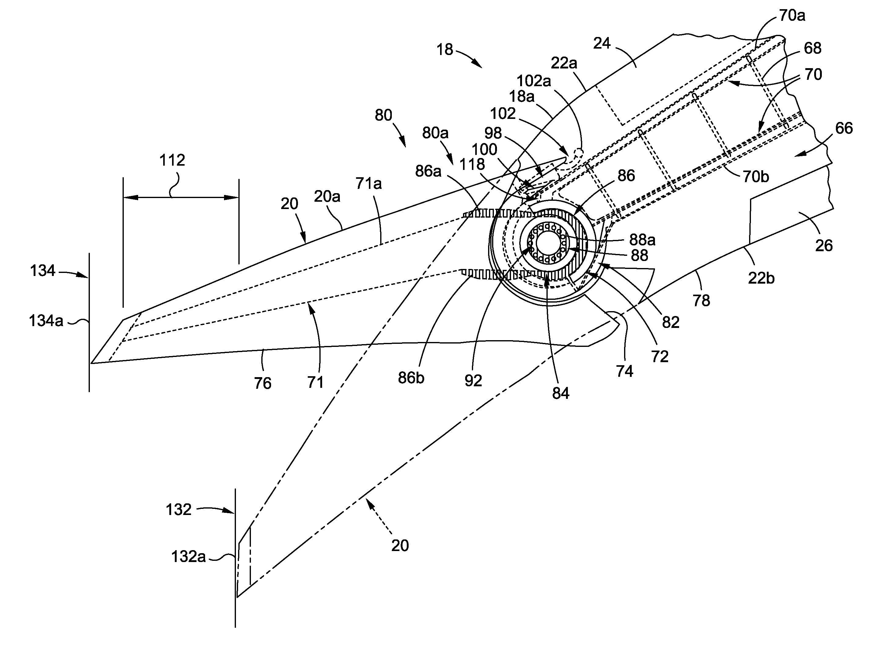
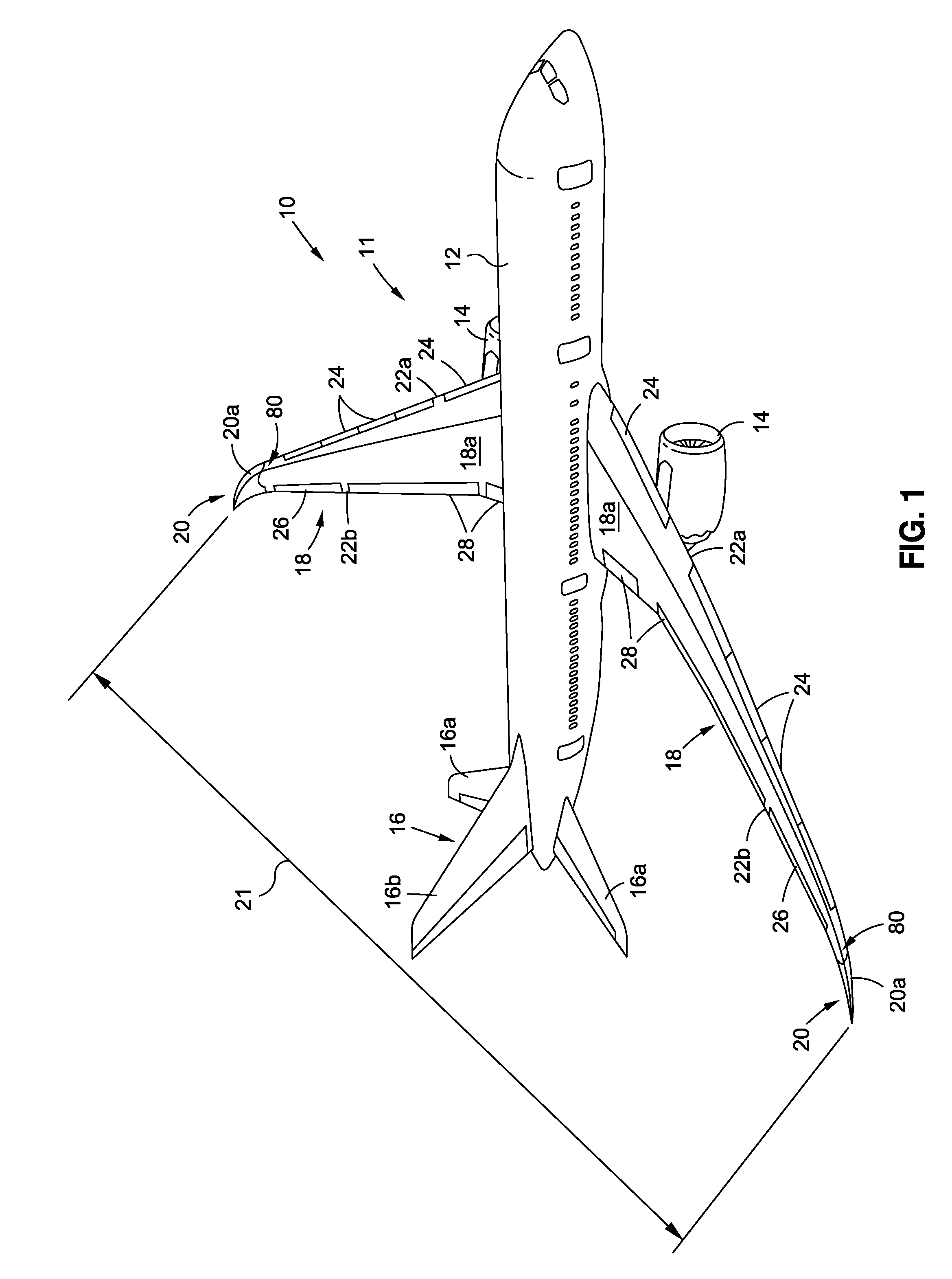
[0046]Now referring to the Figures, FIG. 1 is an illustration of a perspective view of an air vehicle 10 incorporating an exemplary embodiment of a swing wing tip system 80 of the disclosure. As shown in FIG. 1, the air vehicle 10, such as in the form of aircraft 11, comprises a fuselage 12, engines 14, a tail 16 with horizontal stabilizers 16a and a vertical stabilizer 16b, wings 18, such as in the form of swing wings 18a, and wing tips 20, such as in the form of swing wing tips 20a. As further shown in F...


PUM


Abstract

A swing wing tip system for an air vehicle is provided. The swing wing tip system has a swing wing tip assembly with an unfixed wing tip portion movably connected to a fixed wing portion of a wing. The swing wing tip assembly has a dual load path structure configured to transfer load from the unfixed wing tip portion to the fixed wing portion. The dual load path structure has dual wing skin plates and a rotation joint coupled between the dual wing skin plates and configured to rotationally couple the unfixed wing tip portion to the fixed wing portion. The rotation joint has a dual rotation pin element having a center rotation axis and dual rotation elements configured to rotate about the center rotation axis. The swing wing tip system has an actuator assembly coupled to the rotation joint and a controller system coupled to the actuator assembly.

Description

CROSS REFERENCE TO RELATED APPLICATIONS[0001]This nonprovisional patent application is related to U.S. nonprovisional patent application Ser. No. 13 / 530,089, titled “SWING TIP ASSEMBLY ROTATION JOINT”, having Docket Number 11-0872, filed on Jun. 21, 2012, and this nonprovisional patent application is also related to U.S. nonprovisional patent application Ser. No. 13 / 964,072, titled “HORIZONTAL FOLDING WINGTIP”, having Docket Number 12-1633-US-NP, filed on Aug. 10, 2013. The contents of both of these filed U.S. nonprovisional patent applications are hereby incorporated by reference in their entireties.BACKGROUND[0002]1) Field of the Disclosure[0003]The disclosure relates generally to wing systems, assemblies, and methods for air vehicles, and more particularly, to wing tip systems, assemblies, and methods having dual load path structures for air vehicles, such as aircraft.[0004]2) Description of Related Art[0005]Designing an aircraft having a configuration to improve fuel efficiency ...

Claims


Application Information

Patent Timeline
Patent Type & Authority Applications(United States)
IPC IPC(8): B64C9/00
CPCB64C9/00B64C3/40B64C3/56B64C5/14B64C23/072Y02T50/10
Inventor SAKURAI, SEIYAKOSKO, RYAN W.SANTINI, GREGORY M.
Owner THE BOEING CO
Why Eureka
Try Eureka