Reversible monkey wrench

Inactive Publication Date: 2015-04-16
PROXENE TOOLS
View PDF6 Cites 3 Cited by
  • Summary
  • Abstract
  • Description
  • Claims
  • Application Information

AI Technical Summary

Benefits of technology

[0008]The main object of the present invention is to provide a reversible monkey wrench which can prevent the opening width from becoming larger when being turn

Problems solved by technology

In addition, the reversible monkey wrench has a simple structure, and it

Method used


Image

  • Reversible monkey wrench
  • Reversible monkey wrench
  • Reversible monkey wrench

Examples


Embodiment Construction

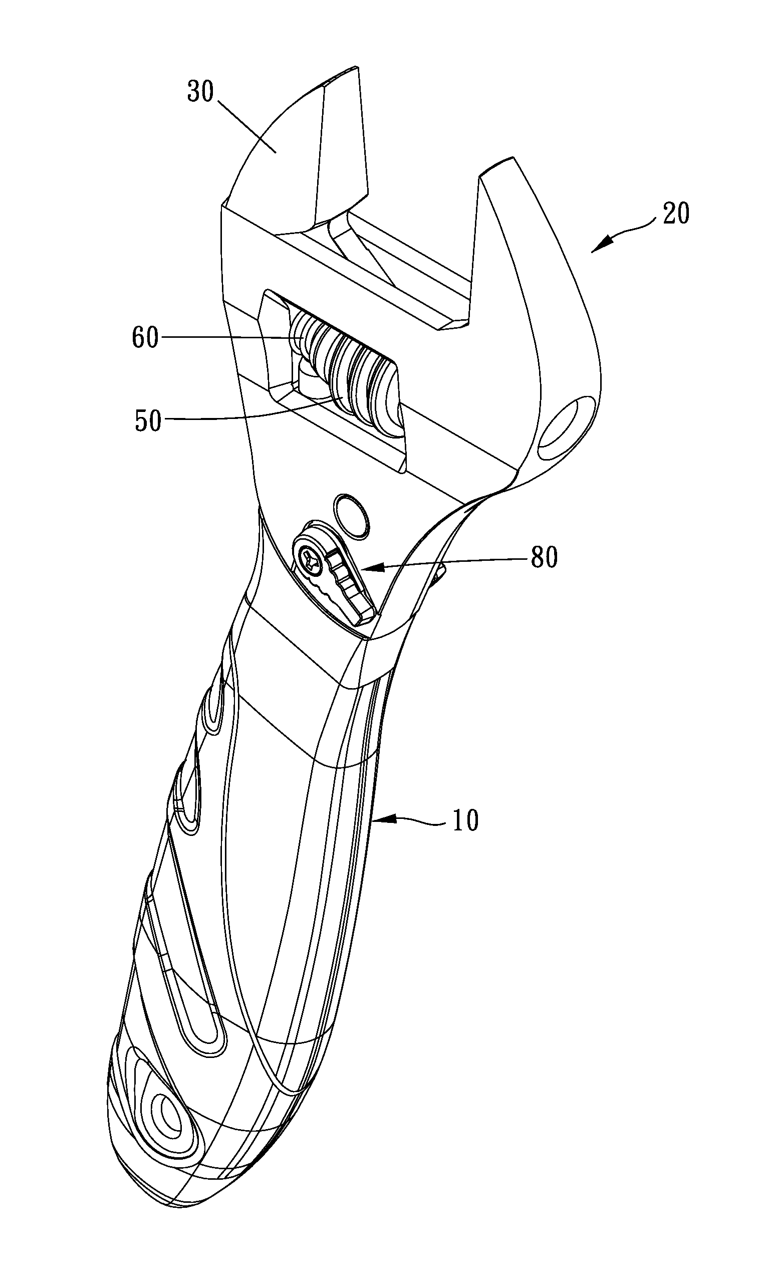
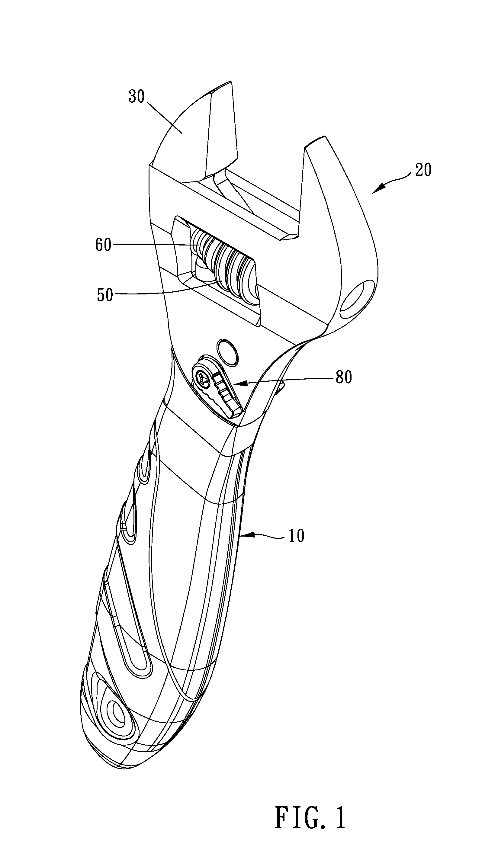
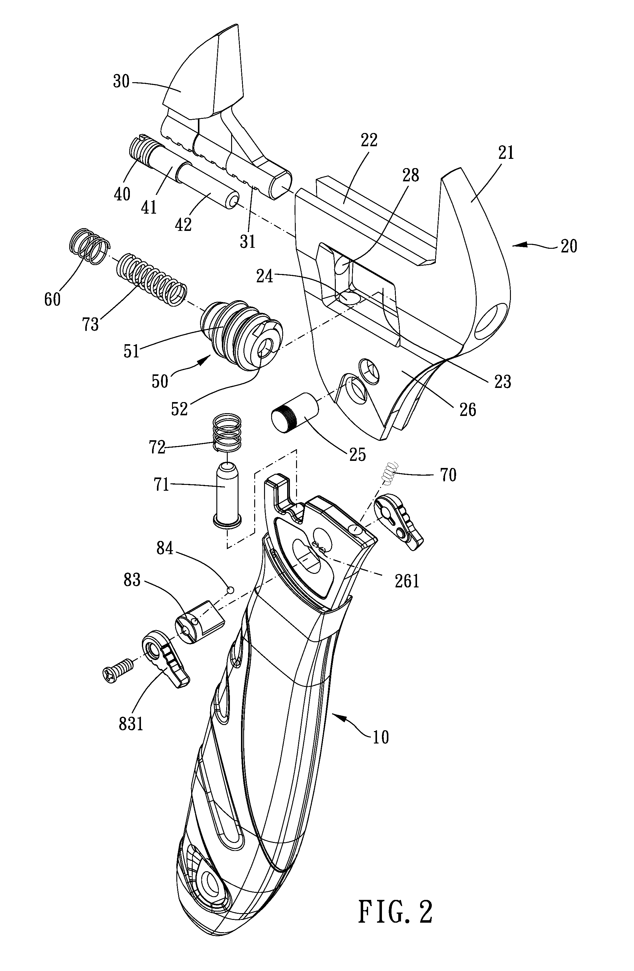
[0026]Please refer to FIGS. 1, 2, 3 and 4 for a first preferable embodiment of the present invention. A reversible monkey wrench of the present invention includes a handle 10, a head 20, a movable jaw 30, an axial rod 40, a worm gear 50 and a dragging mechanism 60.

[0027]The handle 10 is provided for operating and has a connecting end 11, and a driving head (not shown) can be arranged on the other end of the handle 10.

[0028]An end of the head 20 is formed with a fixed jaw 21, a sliding rail 22 transversely disposed, a receiving slot 23 and a connecting bore 24. The receiving slot 23 is communicated with the sliding rail 22. The connecting bore 24 is longitudinally disposed in the head 20 and communicated with the receiving slot 23 and a bottom end of the head 20. The head 20 and the connecting end 11 are swingably connected through a pivot 25. In addition, a pair of wing portions 26 extends from the bottom end of the head 20, and a slot 27 is formed between the wing portions. The con...


PUM


Abstract

A reversible monkey wrench is provided. An end of a head is formed with a fixed jaw, a sliding rail and a receiving slot. The movable jaw has a sliding rod slidably disposed in the sliding rail. The axial rod is disposed in the head and extended into the receiving slot. A worm gear has an engaging portion corresponding to the sliding rod and an axial bore for receiving the axial rod. The worm gear is slidably disposed in the receiving slot and an end thereof is formed with a first dragging portion. A dragging mechanism is disposed around the axial rod and circumferentially contacted with the first dragging portion, dragging portion and friction between the first dragging portion and the dragging mechanism can prevent simultaneous rotation of the worm gear.

Description

BACKGROUND OF THE INVENTION[0001]1. Field of the Invention[0002]The present invention relates to a monkey wrench, and more particularly to a reversible monkey wrench.[0003]2. Description of the Prior Art[0004]Monkey wrenches are one of the most common types of hand tools. Some of them are designed to be reversible, in which they can drive a nut in one direction and run idle in the reverse direction, so that they would not have to disengage from the nut after every turning stroke.[0005]Some reversible monkey wrench is provided with a movable jaw that moves away from the fixed jaw when they are reversely turned, such as disclosed in U.S. Pat. No. 3,312,129, U.S. Pat. No. 5,746,099, and U.S. Pat. No. 6,679,139. These patents disclose a monkey wrench with a worm gear being slidable along with its axial rod.[0006]However, in the conventional reversible monkey wrenches as shown in FIGS. 12 to 15, helical teeth 2 of a worm gear 1 is spiral (from a top view or a side view, the helical teeth...

Claims


Application Information

Patent Timeline
IPC IPC(8): B25B13/24B25B13/14
CPCB25B13/24B25B13/14B25B13/46
Inventor WU, ARTHUR
Owner PROXENE TOOLS
Why Eureka
Try Eureka