
Vacuum equipment for a fiber web machine and a fiber web machine provided with vacuum equipment

a vacuum equipment and fiber web machine technology, applied in the wet end of the machine, papermaking, textiles and papermaking, etc., can solve the problems of fabric wear disadvantageously fast, increase energy consumption, and increase construction cost, so as to reduce production and use costs, the effect of less expensive and more efficien

Active Publication Date: 2013-10-15
VALMET TECH INC
View PDF13 Cites 5 Cited by
  • Summary
  • Abstract
  • Description
  • Claims
  • Application Information

AI Technical Summary

Benefits of technology

This invention provides a better and more efficient vacuum equipment for a fiber web machine that is cheaper to make and use. It uses a plate construction with a raw material thickness that allows for easy machining and has a relatively large opening. This prevents plugging and maintains efficient dewatering. The design is lightweight and rigid, with new properties that allow for a larger efficient dewatering area with low friction and prevents fabric wear and low power requirement. This design can be easily retrofitted and installed without the need for a bridge crane.

Problems solved by technology

Conventionally, the wearing parts of the blades are made of a ceramic material, whereby the construction becomes expensive and sensitive to damage.
This causes friction, which further increases the energy consumption.
In addition, the fabric wears disadvantageously fast.
In practice, it is impossible to increase the slit width due to the fabric wear and increased energy consumption.
A sufficient dewatering efficiency has required high vacuum levels, which leads to high operating costs.
In this case the wearing construction becomes expensive, but a larger dewatering area is achieved with perforated holes compared to blades, without increased felt constriction.
However, a machined wearing construction is expensive, and such long, yet small, holes get gradually plugged.
In practice, the holes must be regularly cleaned, which increases production breaks.
In addition, changing a blade construction into a hole construction is difficult, often even impossible.
Fabric wear may even increase in some cases.

Method used


Image

  • Vacuum equipment for a fiber web machine and a fiber web machine provided with vacuum equipment
  • Vacuum equipment for a fiber web machine and a fiber web machine provided with vacuum equipment
  • Vacuum equipment for a fiber web machine and a fiber web machine provided with vacuum equipment

Examples


Embodiment Construction

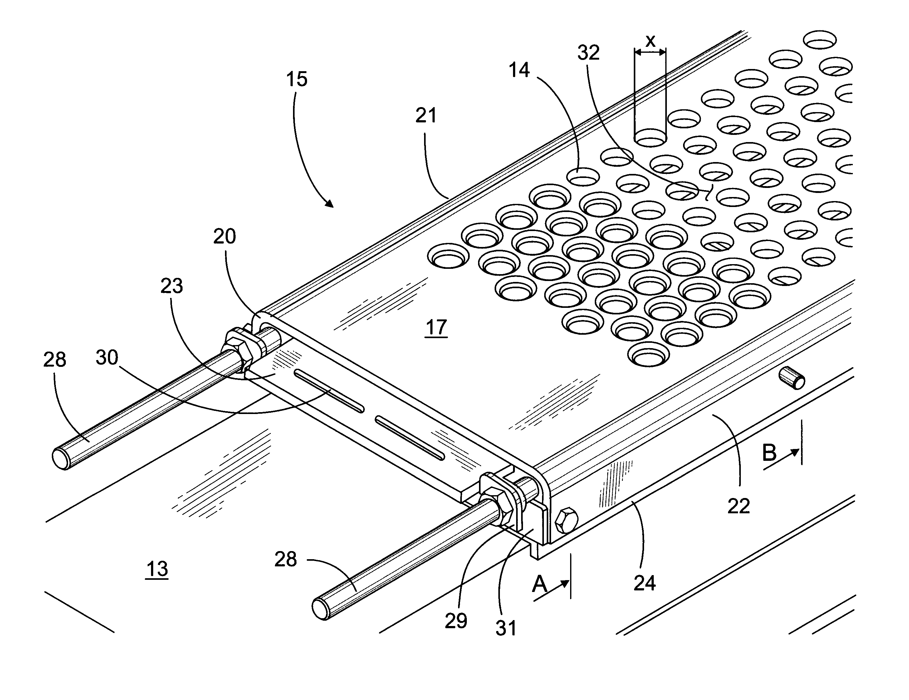
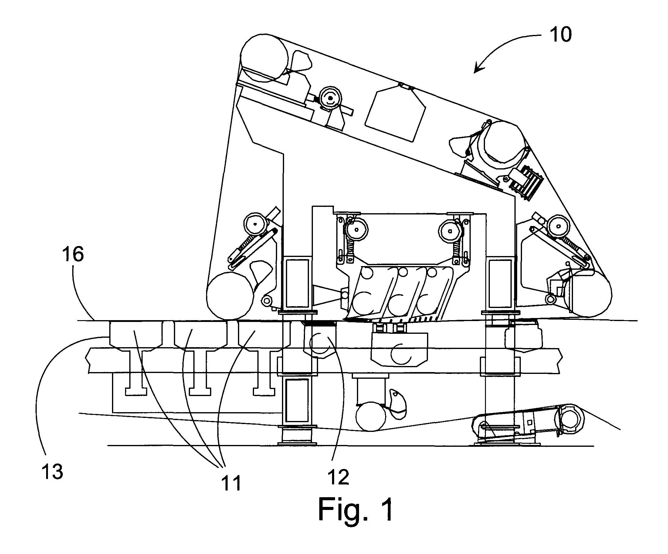
[0016]FIG. 1 illustrates possible applications of the vacuum equipment according to the invention. For example, the forming section 10 of a fiber web machine shown here is provided with various vacuum apparatuses in different positions. The fiber web machine may be, for example, a paper machine or a board machine or another machine suitable for producing a fiber web. The vacuum equipment can be, for example, a low-vacuum suction box 11 or a high-vacuum suction box 12. In the press section following the forming section, the vacuum equipment can be, for example, a felt suction box or a transfer suction box (not shown).

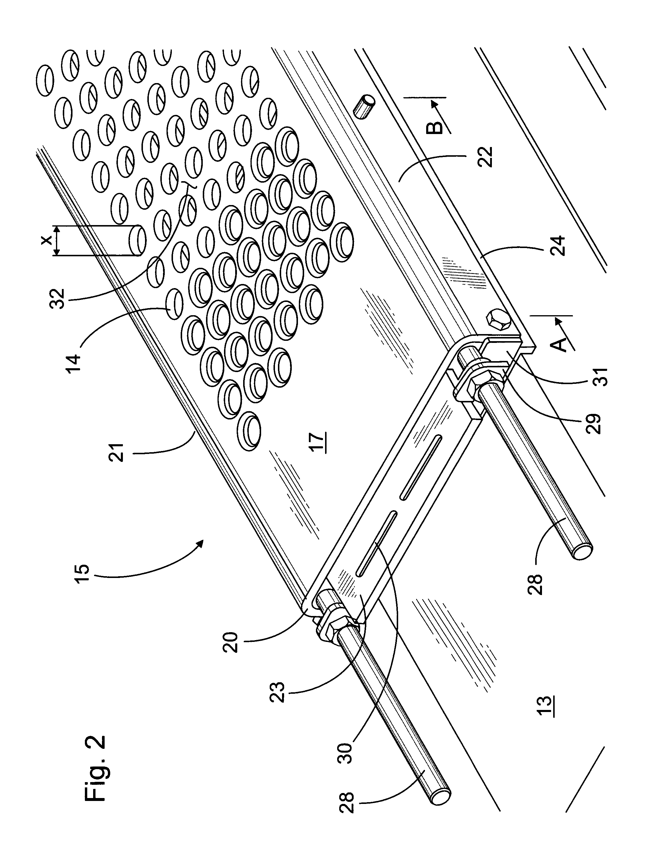
[0017]The vacuum equipment is thus meant particularly for a fiber web machine. Water is removed from the web produced in a fiber web machine in several different ways. Vacuum is also utilized in many positions. Generally, the vacuum equipment includes a frame 13 arranged to be supported to the fiber web machine. The frame usually extends over the entire fabric width and ...


PUM


Abstract

The invention relates to vacuum equipment for a fiber web machine. The vacuum equipment includes a frame (13) arranged to be supported to the fiber web machine. The vacuum equipment also includes a wearing construction (15) adapted to the frame (13) and arranged partially open on the surface by means of several openings (14) for extending a vacuum effect out from within the frame (13) and further to a fabric (16) included in the fiber web machine and set in contact with the wearing construction (15). The wearing construction (15) is a plate construction (17), the raw material thickness s of which is equal to or smaller than the distance x between the opposite edges (18, 19) defining the opening (14). The invention also relates to a fiber web machine provided with vacuum equipment.

Description

CROSS REFERENCES TO RELATED APPLICATIONS[0001]This application is a U.S. national stage application of International App. No. PCT / FI2011 / 050330, filed Apr. 14, 2011, the disclosure of which is incorporated by reference herein and claims priority on Finnish App. No. 20105453, filed Apr. 26, 2010.STATEMENT AS TO RIGHTS TO INVENTIONS MADE UNDER FEDERALLY SPONSORED RESEARCH AND DEVELOPMENT[0002]Not applicable.BACKGROUND OF THE INVENTION[0003]The invention relates to vacuum equipment for a fiber web machine, the vacuum equipment including a frame arranged to be supported to the fiber web machine, and a wearing construction adapted to the frame and arranged partially open on the surface by means of several openings for extending a vacuum effect out from within the frame and further to a fabric included in the fiber web machine and adapted in contact with the wearing construction. The invention also relates to a fiber web machine provided with vacuum equipment.[0004]Vacuum apparatuses are ...

Claims


Application Information

Patent Timeline
Patent Type & Authority Patents(United States)
IPC IPC(8): D21F1/48
CPCD21F1/52D21F1/523D21F1/48
Inventor ERONEN, VILLE H.HYVARINEN, MIIKKATARKIAINEN, VELI-PEKKASAVELA, JYRKI
Owner VALMET TECH INC
Learn More