Fuel cell

a fuel cell and cell technology, applied in the field of fuel cells, can solve the problems of inability to achieve desired power generation, inability to uniformly supply reactant gas through gas distribution channels, and inability to achieve power generation stably, etc., to achieve uniformity, simple structure, and reliably supply the effect of reactant gas

Inactive Publication Date: 2010-06-15
HONDA MOTOR CO LTD
View PDF7 Cites 7 Cited by
  • Summary
  • Abstract
  • Description
  • Claims
  • Application Information

AI Technical Summary

Benefits of technology

[0011]A main object of the present invention is to provide a fuel cell having simple structure in which it is possible to uniformly and reliably supply a reactant gas from a reactant gas passage to the entire reactant gas flow field through a buffer, and maintain the suitable power generation performance.
[0017]According to the present invention, the grooves of the first buffer area adjacent to the reactant gas passage are deeper than the grooves of the second buffer area adjacent to the reactant gas flow field in the stacking direction. Thus, in the structure, for example, the reactant gas supplied from the reactant gas passage to the first buffer area is distributed uniformly over the first buffer area. Even if the width of the opening of the reactant gas passage is small, by the first buffer area having the deep grooves near the reactant gas passage, in effect, the width of the opening of the reactant gas passage becomes large. Accordingly, the reactant gas can be supplied uniformly and reliably from the reactant gas passage to the entire reactant gas flow field through the buffer.
[0019]Accordingly, variation in power generation due to decrease in the flow rate of the fuel gas, and generation of the concentration overpotential is prevented reliably, and the desired power generation performance is achieved stably.

Problems solved by technology

Thus, it is not possible to uniformly supply the reactant gas through the gas distribution channels 4a along the width of the reactant gas flow field 3a.
Thus, when the load is small, power generation cannot be performed stably due to the water remaining in the fuel cell.
When the load is large, concentration overpotential occurs due to shortage of the reactant gas, and the desired power generation cannot be achieved.

Method used


Image

  • Fuel cell
  • Fuel cell
  • Fuel cell

Examples


Embodiment Construction

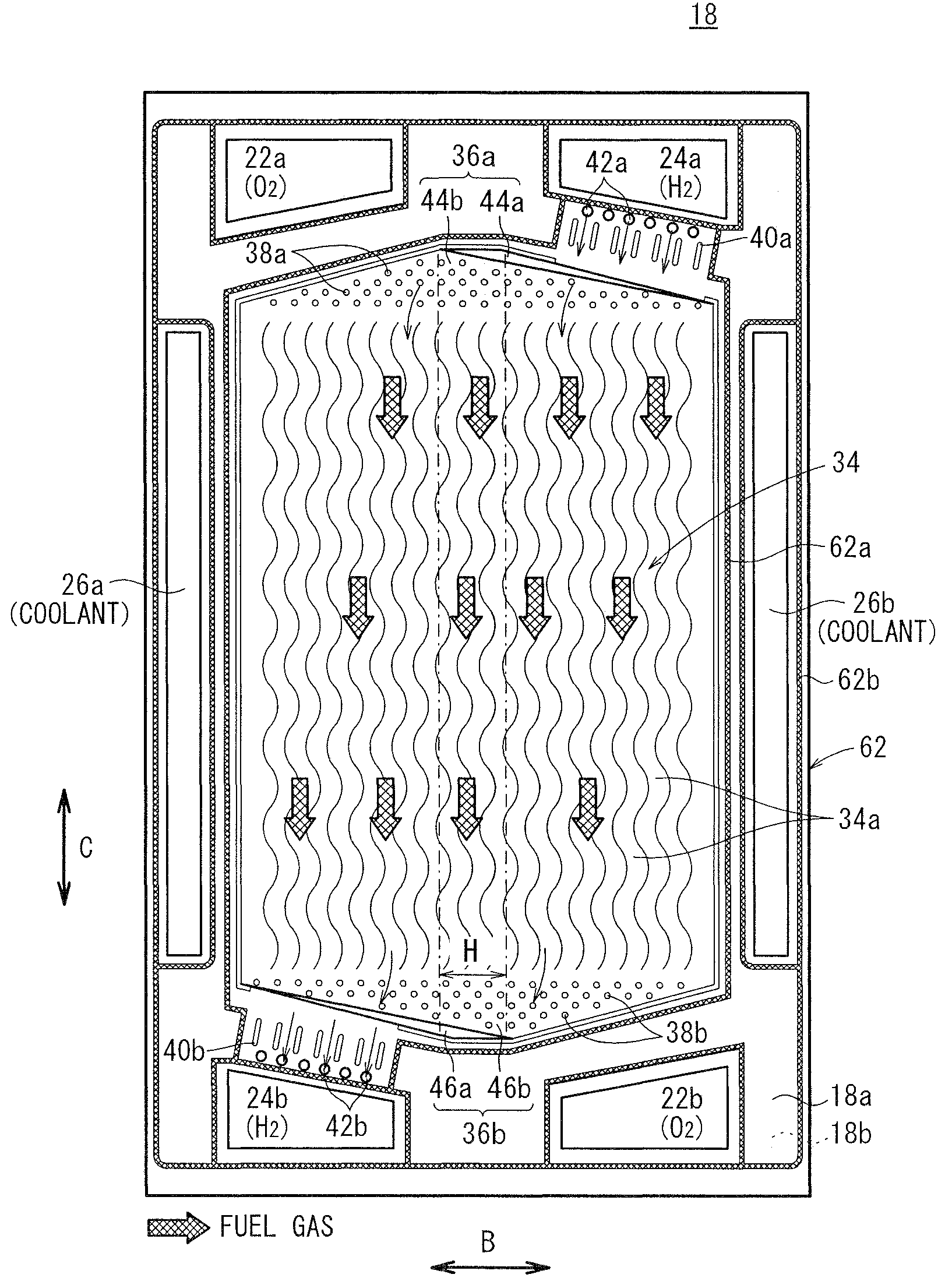
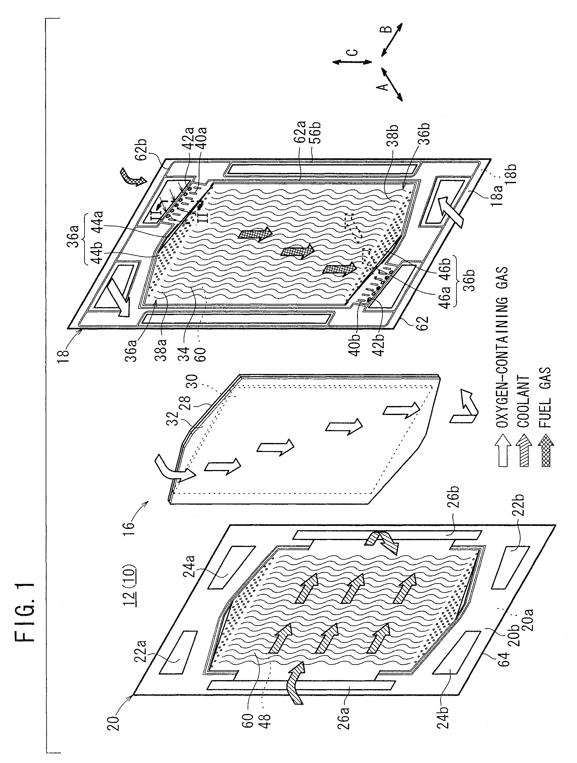
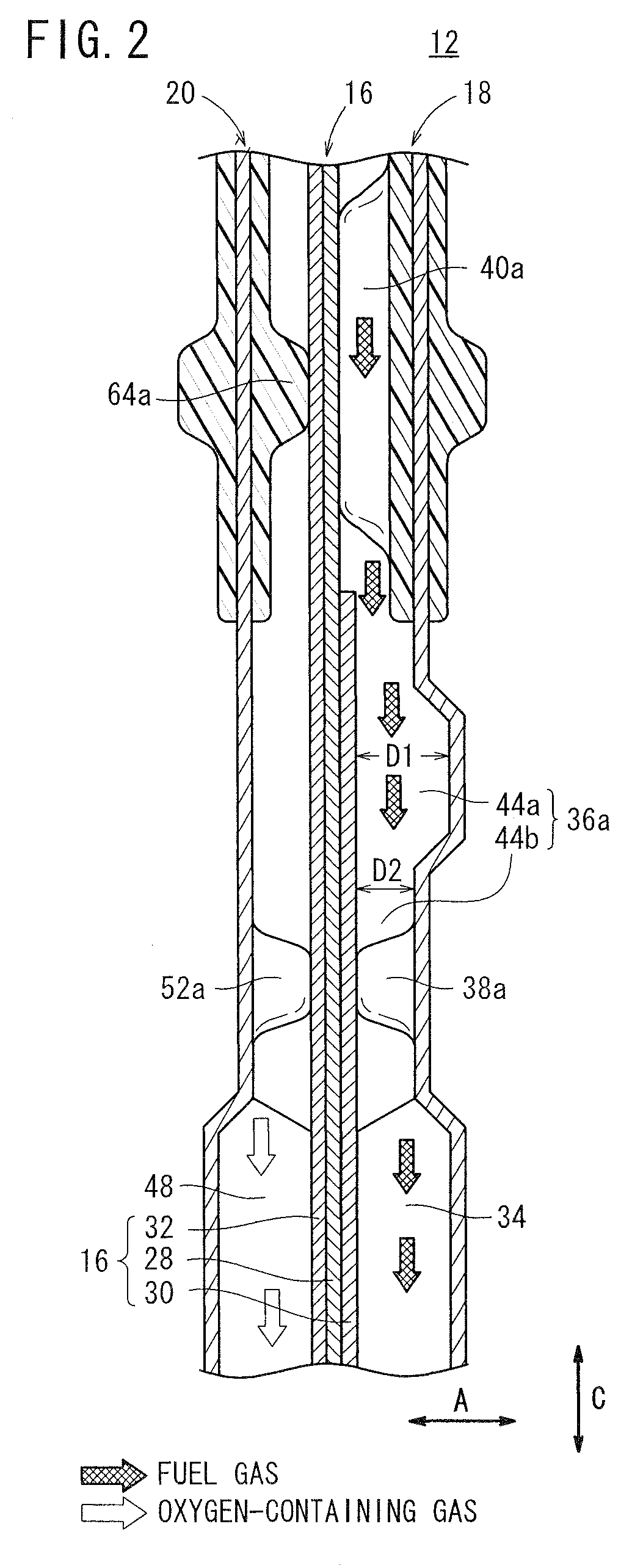
[0026]FIG. 1 is an exploded perspective view schematically showing a power generation cell 12 of a fuel cell 10 according to an embodiment of the present invention. FIG. 2 is a cross sectional view taken along a line II-II in FIG. 1, showing the power generation cell 12.

[0027]The fuel cell 10 is formed by stacking a plurality of the power generation cells 12 in a direction indicated by an arrow A. At opposite ends of the fuel cell 10 in the stacking direction, end plates (not shown) are provided. The stacked power generation cells 12 between the end plates are fixed together by tie rods (not shown). Alternatively, the power generation cells 12 are placed in a casing (not shown), and a predetermined tightening load is applied to the power generation cells 12 in the direction indicated by the arrow A.

[0028]As shown in FIG. 1, each of the power generation cells 12 includes a membrane electrode assembly 16 and an anode side first metal separator 18 and a cathode side second metal separa...


PUM

PropertyMeasurementUnit
areaaaaaaaaaaa
widthaaaaaaaaaa
gravityaaaaaaaaaa

Abstract

An oxygen-containing gas supply passage and an oxygen-containing gas discharge passage extend through a set of diagonal positions of a first metal separator, and a fuel gas supply passage and a fuel gas discharge passage extend through the other set of diagonal positions of the first metal separator. A fuel gas flow field is connected to the fuel gas supply passage through an inlet buffer at an upper position, and connected to the fuel gas discharge passage through an outlet buffer at a lower position. The inlet buffer includes a first inlet buffer area adjacent to the fuel gas supply passage and a second inlet buffer area adjacent to the fuel gas flow field. Grooves of the first inlet buffer area are deeper than grooves of the second inlet buffer area in the stacking direction.

Description

BACKGROUND OF THE INVENTION[0001]1. Field of the Invention[0002]The present invention relates to a fuel cell formed by stacking a membrane electrode assembly and a separator in a stacking direction. The membrane electrode assembly includes a pair of electrodes, and an electrolyte interposed between the electrodes. A reactant flow field is formed in the fuel cell for supplying a reactant gas along an electrode surface.[0003]2. Description of the Related Art[0004]For example, a solid polymer electrolyte fuel cell employs a membrane electrode assembly (electrolyte electrode assembly) which includes an anode, a cathode, and a solid polymer electrolyte membrane interposed between the anode and the cathode. The electrolyte membrane is a polymer ion exchange membrane. The membrane electrode assembly is sandwiched between separators to form a power generation cell (unit cell). In use on a vehicle, several tens to hundreds of the unit cells are stacked together to form a fuel cell stack.[000...

Claims


Application Information

Patent Timeline
Patent Type & Authority Patents(United States)
IPC IPC(8): H01M2/18H01M2/00H01M8/00H01M2/14
CPCH01M8/026Y02E60/50H01M2008/1095H01M8/0263
Inventor ODA, MASARUMOHRI, MASAHIROOHTA, HIROAKIWATANABE, YASUHIROTANIMOTO, SATOSHISAITO, NOBUHIRO
Owner HONDA MOTOR CO LTD
Why Eureka
Try Eureka