Mounting device for mounting a flexible tank inside a compartment

a technology for mounting devices and flexible tanks, which is applied in the direction of containers, transportation items, items transportation vehicles, etc., can solve the problems of difficult access to the lower portion of the tank, difficulty in fitting the compartment, and difficulty in adjusting the tank to fit the compartment, so as to reduce the time required and simplify the installation

Inactive Publication Date: 2015-04-16
EUROCOPTER
View PDF10 Cites 11 Cited by
  • Summary
  • Abstract
  • Description
  • Claims
  • Application Information

AI Technical Summary

Benefits of technology

[0025]An object of the present invention is thus to propose a mounting device for mounting a flexible tank inside a compartment that enables the above-mentioned limitations to be overcome. The mounting device should thus make it possible to simplify installing and removing the lacing system for lacing a flexible tank, thereby reducing the time required for those operations and their arduousness for an operator.
[0026]The mounting device should also make it possible to improve the shaping of the flexible tank, firstly by increasing the number of edges of the tank that are suitable for being provided with a lacing system, and secondly by facilitating tensioning of the lacing system.
[0027]Finally, the mounting device should make it possible to maintain the impact resistance and crash resistance properties of the flexible tank and should not have any major impact on the weight of the mounting device and on the weight of the flexible tank.

Problems solved by technology

However, such a lacing system is particularly cumbersome to put in place since the lacing is performed manually by an operator who must be inside the aircraft.
In addition, the cord can generally be put into place on the upper portion of the tank only, the lower portion being too difficult of access for such manual operations to be performed once the tank is in place inside the compartment.
As a result, the extent to which the tank can be adjusted to fit the compartment is limited, since the skin of the tank can be tensioned in its upper portion only.
In addition, not having any folds in the skin of the tank at the bottom of the compartment or on any other face of the tank reduces the risks of the skin of the tank being degraded over time.
This lacing operation is tedious and arduous for the operator, but it is essential and requires a considerable amount of time for installation and removal.

Method used


Image

  • Mounting device for mounting a flexible tank inside a compartment
  • Mounting device for mounting a flexible tank inside a compartment
  • Mounting device for mounting a flexible tank inside a compartment

Examples


Embodiment Construction

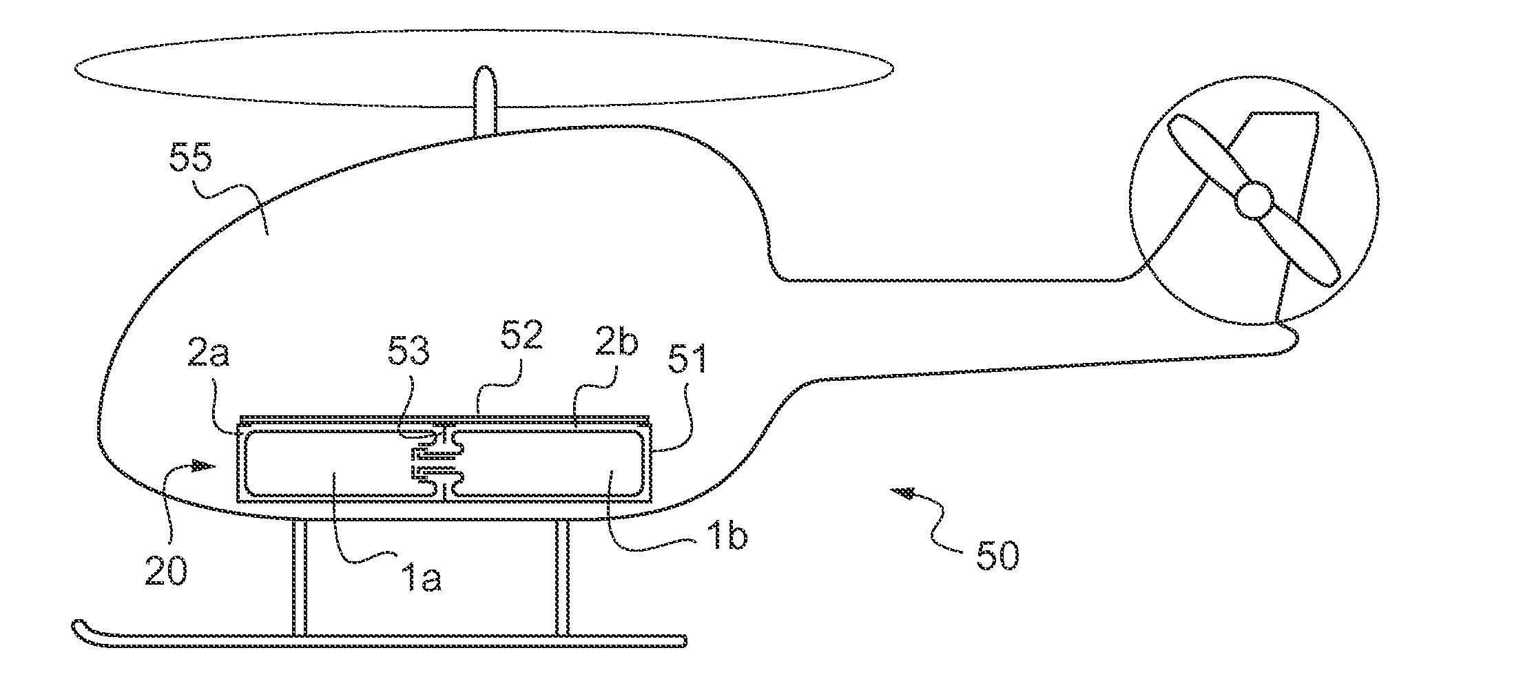
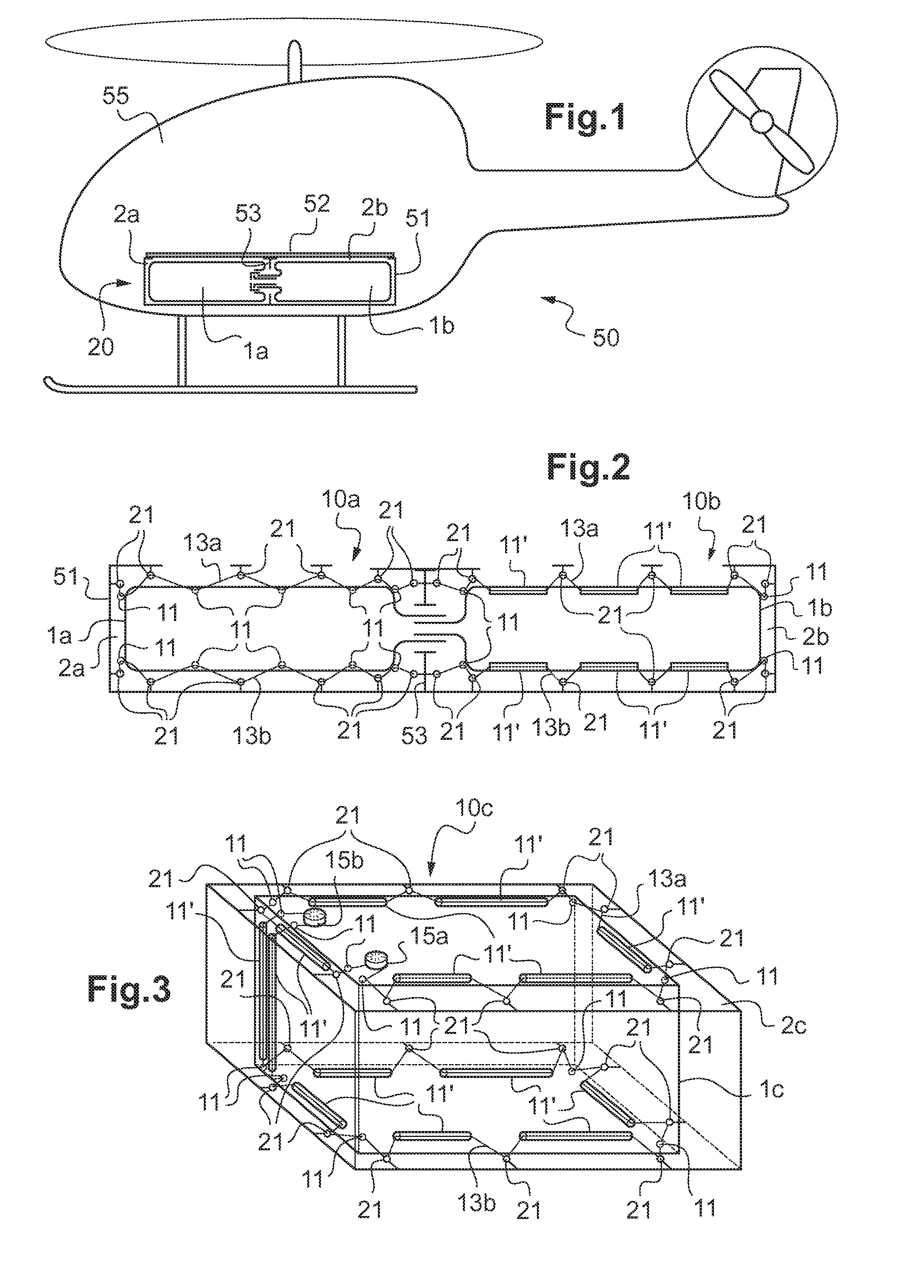
[0085]FIG. 1 shows an aircraft 50 including a lower structure 51 below a cabin 55, a floor 52 covering the lower structure 51, and a fuel storage system 20 situated inside the lower structure 51. This fuel storage system 20 comprises two compartments 2a, 2b separated by a structural partition 53 and two flexible tanks 1a, 1b disposed in respective ones of the compartments 2a, 2b.

[0086]In addition, a fuel storage system 20, comprising at least one compartment 2a, 2b and at least one flexible tank 1a, 1b, may also be situated in one or more vertical structures of the aircraft 50, such as transverse or lateral partitions.

[0087]FIG. 2 shows the fuel storage system 20 comprising two flexible tanks 1a, 1b that are substantially rectangular block shaped and that are situated in respective ones of the compartments 2a, 2b. Each flexible tank 1a, 1b is mounted and shaped inside its respective compartment 2a, 2b by a respective mounting device 10a, 10b.

[0088]Such a mounting device 10c of a f...


PUM


Abstract

A mounting device (10c) for mounting a flexible tank (1c) inside a compartment (2c), said fastening device (10c) comprising: a plurality of first fastening elements (11, 11′) secured to said flexible tank (1c), a plurality of second fastening elements (12) secured to said compartment (2c); and at least one cable (13a, 13b). Each cable (13a, 13b) passes through first fastening elements (11, 11′) and through second fastening elements (12) to shape and to mount said flexible tank (1c) inside said compartment (2c). Said mounting device (10c) further comprises at least one reversible tightening means (15a, 15b) for reversibly tightening said cable (13a, 13b), making it possible to tighten and to slacken said cable (13a, 13b).

Description

CROSS REFERENCE TO RELATED APPLICATION[0001]This application claims priority to French patent application No. FR 13 02368 filed on Oct. 11, 2013, the disclosure of which is incorporated in its entirety by reference herein.BACKGROUND OF THE INVENTION[0002](1) Field of the Invention[0003]The present invention relates to the field of fluid storage means, and in particular to installing such means.[0004]The present invention relates to a mounting device for mounting a flexible tank inside a compartment, the mounting device being designed more particularly for a flexible fuel tank of a rotary-wing aircraft.[0005]The present invention also relates to a fuel storage system using such a mounting device, and to a rotary-wing aircraft using such a fuel storage system.[0006](2) Description of Related Art[0007]Aircraft, and in particular rotary-wing aircraft, have at least one and generally more than one fuel tank. Each tank is generally flexible and is housed in a respective compartment. Each ...

Claims


Application Information

Patent Timeline
Patent Type & Authority Applications(United States)
IPC IPC(8): B64D37/04
CPCB64D37/04B64D37/06
Inventor BORNES, SYLVAIN
Owner EUROCOPTER
Why Eureka
Try Eureka