Tool joint

a tool head and tool head technology, applied in the field of tool heads, can solve the problem that they cannot be used for some backup driving parts, and achieve the effect of preventing the tool head from falling from the assembly slo

Inactive Publication Date: 2015-04-16
CHAN FU YI
View PDF15 Cites 13 Cited by
  • Summary
  • Abstract
  • Description
  • Claims
  • Application Information

AI Technical Summary

Benefits of technology

[0013]Compared with conventional tool joints, the assembly slot of the second main body of the present invention is mounted with a tool head. Then the tool head is locked by each locking member. Thus the tool head is mounted firmly, not easily falling off from the assembly slot of the second main body. The second main body is moved toward the bottom end of the mounting part of the first main body and each locking member is no more against the stopping part of the first main body. The receiving means is moved by elasticity of the second elastic member. Then the receiving means further pushes the tool head to move outward along the first main body axially. The tool head will not fall off from the assembly slot and the user can hold and move the tool head from the first main body manually. Thus the falling of the tool head from the assembly slot can be prevented. The second main body is received in the mounting part of the first main body. While the tool head being falling off, the second main body is protected by the first main body, without being bumped and the tool head is automatically released from the assembly slot of the second main body.

Problems solved by technology

However, the tool holder revealed in the U.S. Pat. No. 3,398,965 is only suitable for a sleeve workpiece with an extension end where the force is applied to.
It's unable to be used for some backup driving parts such as stubby screwdriver.
Thus the tubular tool receiving bushing is idly rotated in the cylindrical inner wall of the shank and is unable to drive the screwdriver.

Method used


Image

  • Tool joint
  • Tool joint
  • Tool joint

Examples


Embodiment Construction

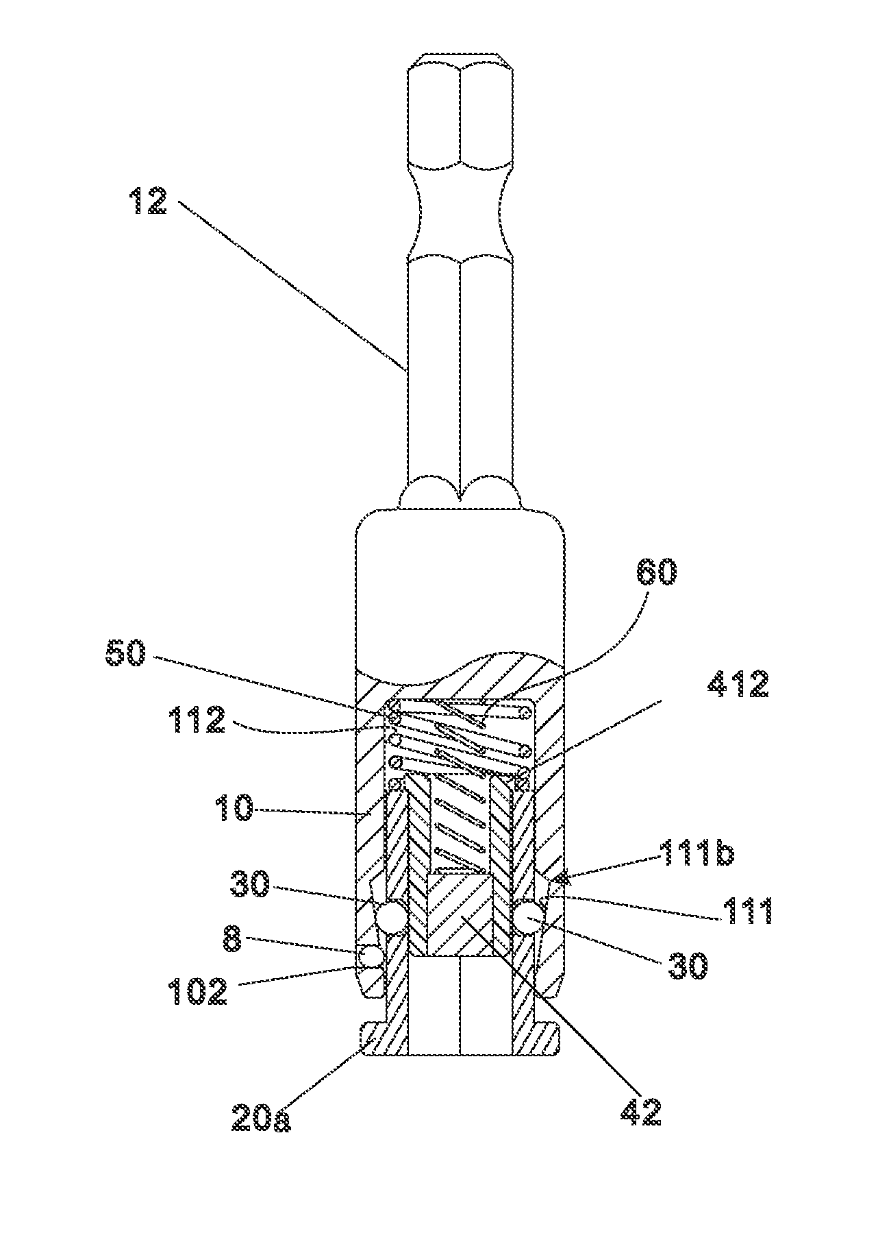
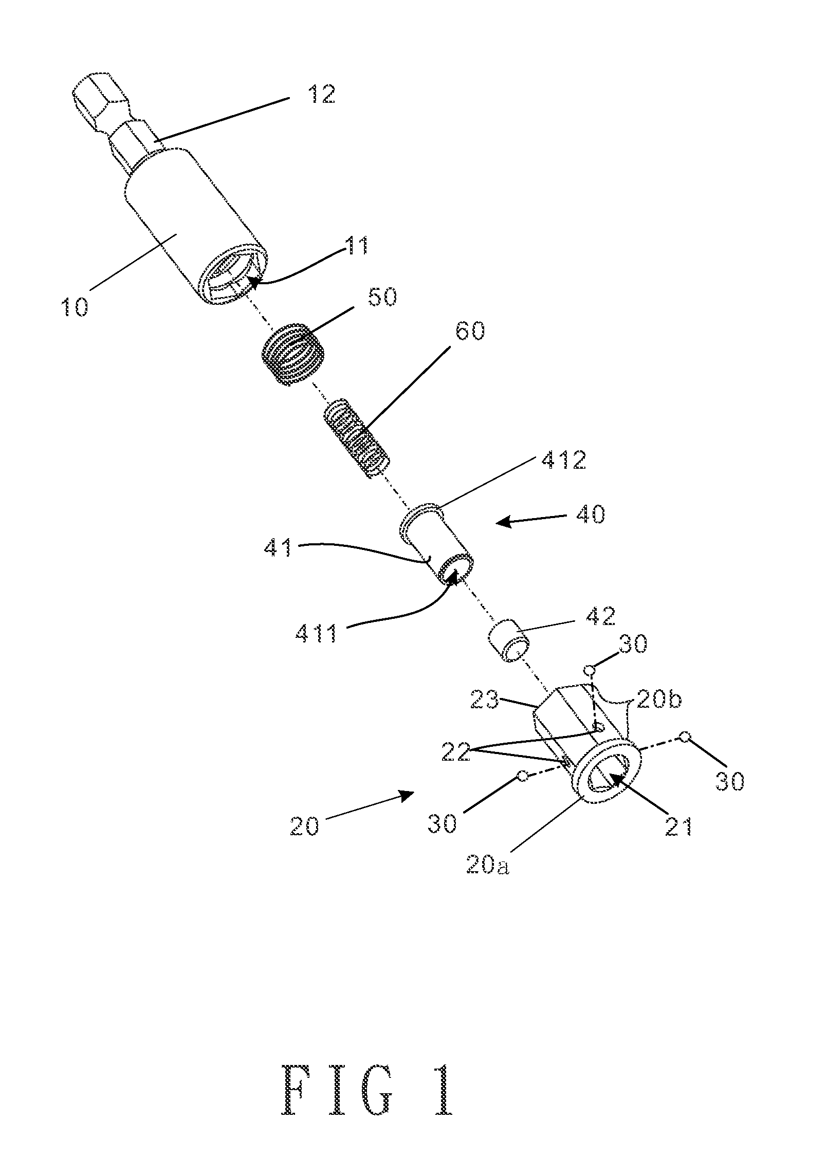
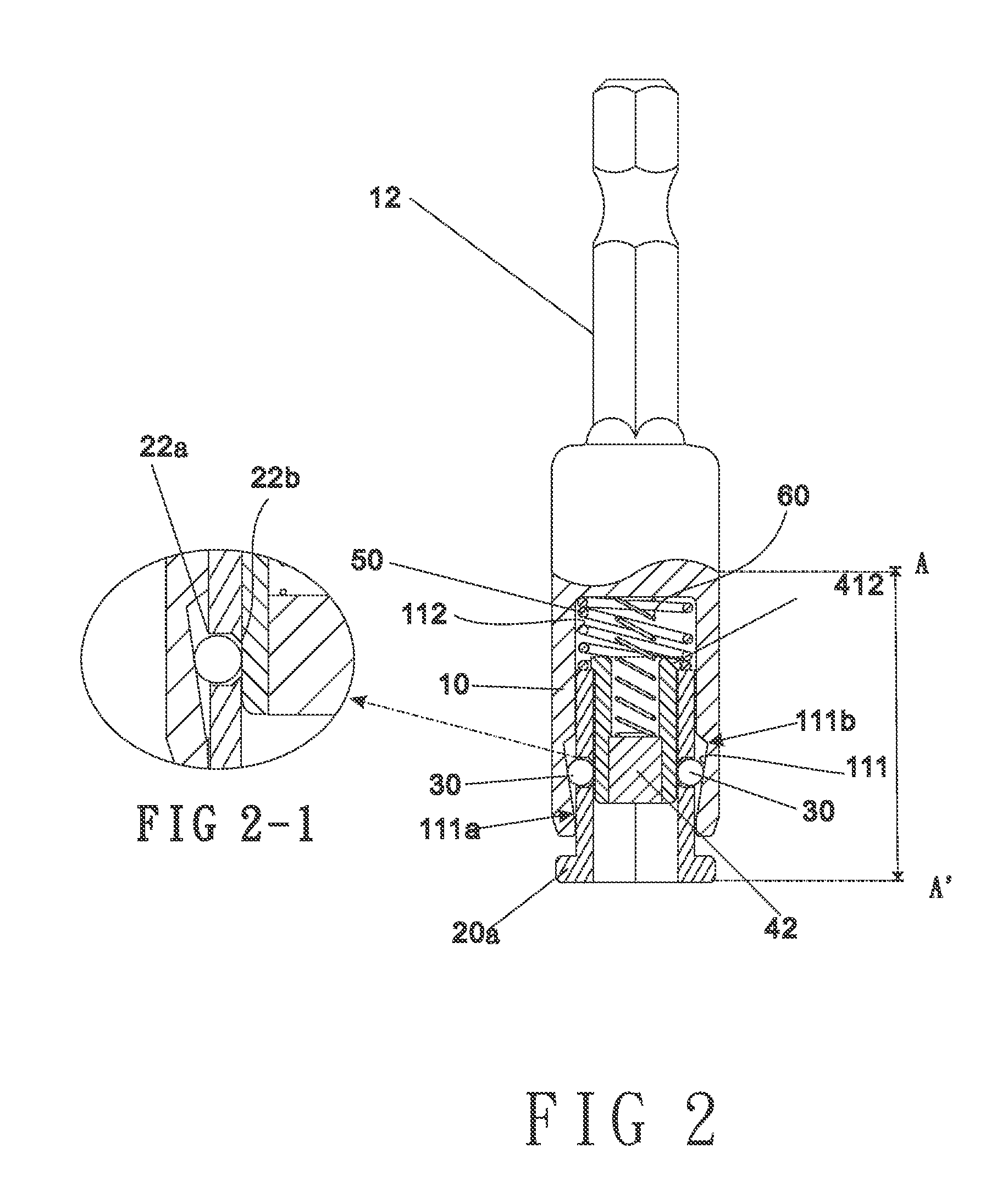
[0026]Refer from FIG. 1 to FIG. 4, a tool joint of the present invention includes a first main body 10, a second main body 20, at least one locking member 30, a sleeve set 40, a first elastic member 50, and a second elastic member 60.

[0027]One end of the first main body 10 is disposed with a mounting part 11 while the other end thereof is arranged with a driving part 12. The mounting part 11 consists of a front end 11a, a stopping part 111, and a rear part 112. The front end 11a is extended inward to form the stopping part 111 and the stopping part 111 is further extended to form the rear part 112. The front end 11a and the rear part 112 are polygonal slots with polygonal cross section. In this embodiment, the front end 11a and the rear part 112 of the mounting part 11 are slots with hexagonal cross section. The stopping part 111 close to an opening end of the mounting part 11 is a circular groove having a front segment 111a and a rear segment 111b. The diameter of the front segment...


PUM


Abstract

A tool joint is revealed. The tool joint includes a first main body, a second main body, locking members and a sleeve set. The first main body consists of a mounting part, a stopping part and a rear part. The second main body is disposed in the mounting part and having a polygonal assembly slot penetrating the second main body. Insertion holes are disposed close to an opening end of the assembly slot. The second main body is a polygonal column whose shape matches that of the polygonal assembly slot. The locking member is against the stopping part. The sleeve set is mounted in the assembly slot. The tool joint features on that the second main body is unable to rotate radially in the mounting part by the polygonal column design of the second main body locked with walls of a polygonal slot of the mounting part.

Description

BACKGROUND OF THE INVENTION[0001]1. Fields of the Invention[0002]The present invention relates to a tool joint, especially to a tool joint that connects to passive tools such as screwdrivers. The tool joint includes a first main body, a second main body, locking members and a sleeve set. The second main body and the sleeve set are movable in the first main body elastically and axially. The assembly of the above components is easy.[0003]2. Descriptions of Related Art[0004]Refer to U.S. Pat. No. 3,398,965, a quick change tool holder is revealed. A tool holder includes a shank member and a tubular tool receiving bushing. The shank member has a tapered portion and an open ended tubular portion with a cylindrical inner wall in which the tubular tool receiving bushing has a sliding fit. An inner end of the tubular portion of the shank is a non-cylindrical tool driving portion adapted to receive the end of a tool. Three circumferentially spaced apart ball retaining apertures are extending ...

Claims


Application Information

Patent Timeline
Patent Type & Authority Applications(United States)
IPC IPC(8): B25B23/00B23B31/22
CPCB25B23/0035B23B31/22Y10T279/17743Y10T279/17752
Inventor CHAN, FU-YI
Owner CHAN FU YI
Why Eureka
Try Eureka