Head-mounted stereoscopic display

a stereoscopic display and head-mounted technology, applied in the field of head-mounted stereoscopic displays, can solve the problems of limiting the commercialization of products, high price of products, and inability of common computer displays and television displays to meet the needs of video game players

Inactive Publication Date: 2015-04-16
BEIJING ANTVR TECH
View PDF5 Cites 68 Cited by
  • Summary
  • Abstract
  • Description
  • Claims
  • Application Information

AI Technical Summary

Benefits of technology

[0026]Preferably, the clamping components are provided with one or more slots arranged respective...

Problems solved by technology

However, common computer displays and television displays cannot meet the needs of the video game players.
Such products are expensive while the resolution is low, which limits the commercialization of the products.
But the distance from the displays to the lens is less than 50 mm, and the focal length of the lens is very short, so the images must be firstly deformed into spherical images to be showed so as to correc...

Method used


Image

  • Head-mounted stereoscopic display
  • Head-mounted stereoscopic display
  • Head-mounted stereoscopic display

Examples


first embodiment

[0064]a. In the first embodiment as shown in FIG. 7a, when the face-mask unit 601 and the optical base unit 602 are combined as a single body, the optical base unit 602 connects with the face-mask unit 601 by inserting a protruding pivot 604 in the optical base unit 602 into the corresponding notch 603 on top of the face-mask unit 601, and then the optical base unit 602 and the face-mask unit 601 are combined by rotating the optical base unit 602 downwards around the pivot 604 to insert the protruding portion 605 at the bottom of the optical base unit 602 into the corresponding engagement notch 606 of the face-mask unit 601. To detach the optical base unit 602 from the face-mask unit 601, a unlock button 701 protruding from the bottom of the optical base unit 602 is pushed up, the protruding portion 605 and the engagement notch 606 are released to disengage the combination into two parts, and then the optical base unit 602 is rotated upward around the pivot 604 to make the pivot 604...

second embodiment

[0065]b. In the second embodiment as shown in FIG. 7b, the face-mask unit 601 and the optical base unit 602 are provided with magnetic connectors 702 and 702′ on the opposite sides. When the face-mask unit 601 and the optical base unit 602 are combined as a single body, the optical base unit 602 connects with the face-mask unit 601 by inserting the protruding pivot 604 in the optical base unit 602 into the corresponding notch 603 on top of the face-mask unit 601, and then the optical base unit 602 and the face-mask unit 601 are combined by rotating the optical base unit 602 downwards around the pivot 604 to make the magnetic connector 702 and 702′ engage with each other tightly. To separate the face-mask unit 601 and the optical base unit 602, the optical base unit 602 is pushed outward so as to disengage the magnetic connector 702 and 702′, and then the optical base unit 602 is rotated upward around the pivot 604 to make the pivot 604 separate from the notch 603 of face-mask unit 6...

third embodiment

[0066]c. In the third embodiment as shown in FIG. 7c, the face-mask unit 601 and the optical base unit 602 comprise a T-shaped notch 703 and a T-shaped protruding portion 703′ respectively which are engaged by inserting T-shaped protruding portion 703′ into the T-shaped notch 703 from the top.

Structure of External Observation Window

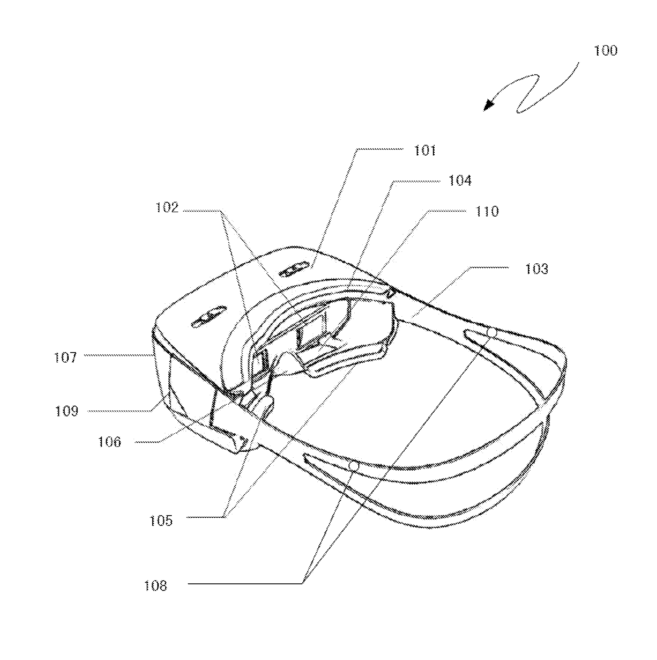
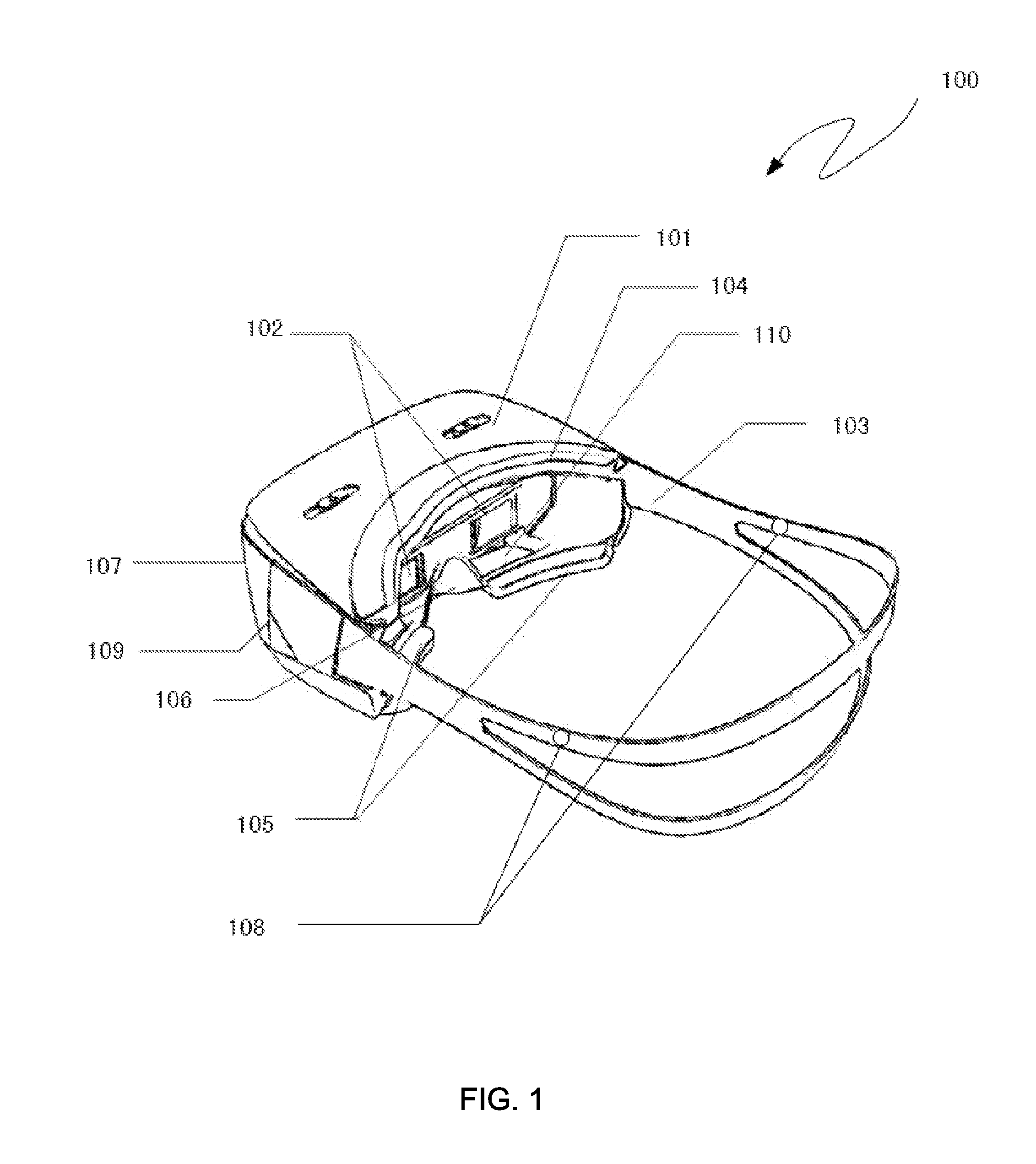
[0067]FIG. 8 illustrates an observation window 110 which is convenient for the user to look outwards when wearing the head-mounted base unit 101. A pair of observation windows 110 is provided in the cheek-supporting part 105 in the lower part of the head-mounted base unit 101, corresponding to the left and the right display units and corresponding to the places where the left and the right eye can look downwards outside. According to an embodiment of the present invention, the pair of observation windows 110 may be covered with a pair of sliding light-blocking covers 801, so that the light-blocking cover 801 covers the observation window 110 for blocking ...


PUM


Abstract

The present invention provides a head-mounted stereoscopic display comprises a head-mounted base unit, a single display unit arranged on the side facing away from the human face inside the head-mounted base unit for presenting images to human eyes, optical magnifying lens which are arranged on the side near the human face of the head-mounted base unit, and the annular headband which is connected with the head-mounted base unit and extending around user's head for fixing the head-mounted base unit, the head-mounted base unit comprises a face-mask unit and an optical base unit, the face-mask unit fits with human face tightly, and the optical base unit fixes the display unit and the optical magnifying lens, the single display unit displays two different images for the left and right eyes respectively side by side simultaneously.

Description

CROSS-REFERENCE TO RELATED APPLICATIONS[0001]This non-provisional application claims priority under 35 U.S.C. §119(a) on Patent Application No. 201320630596.4 filed in P.R. China on Oct. 13, 2013, Patent Application No. 201310646979.5 filed in P.R. China on Dec. 4, 2013, Patent Application No. 201420172689.1 filed in P.R. China on Apr. 10, 2014, Patent Application No. 201420273628.4 filed in P.R. China on May 27, 2014, the entire contents of which are hereby incorporated by reference.TECHNICAL FIELD[0002]The present invention relates to a head-mounted stereoscopic display for immersion visual experience in the field of virtual reality.BACKGROUND OF THE INVENTION[0003]Nowadays, electronics games become more and more popular with the development of electronics technology. However, common computer displays and television displays cannot meet the needs of the video game players. Thus a new type of a head-mounted near-eye display appears in the market, so the user can see the screen thro...

Claims


Application Information

Patent Timeline
IPC IPC(8): H04N13/04
CPCH04N13/044G02B13/08G02B27/0172G02B27/0176G02B2027/011G02B2027/0136H04N13/344
Inventor QIN, ZHENG
Owner BEIJING ANTVR TECH
Why Eureka
Try Eureka