
System and method for controlling a tracking autofocus (TAF) sensor in a machine vision inspection system

a technology of tracking autofocus and inspection system, which is applied in the field of systems and methods for controlling the tracking autofocus (taf) sensor in the machine vision inspection system, can solve the problems of difficult to achieve in a timely manner, and achieve the effect of high throughpu

Active Publication Date: 2015-04-16
MITUTOYO CORP
View PDF8 Cites 17 Cited by
  • Summary
  • Abstract
  • Description
  • Claims
  • Application Information

AI Technical Summary

Benefits of technology

The patent describes a method for controlling the operation of a Tracking AutoFocus (TAF) portion of a machine vision inspection system. The TAF portion automatically adjusts the focus position of the system based on the surface height of the workpiece being inspected. The method includes providing a TAF enable and disable operations, with the TAF disable operations being triggered when the TAF portion exceeds a certain threshold. The TAF disable operations can include a TAF holding mode that allows for selective suspension or holding of the TAF portion. The technical effect of this patent is to improve the efficiency and accuracy of inspection systems by automatically adjusting focus position based on the surface height of the workpiece being inspected.

Problems solved by technology

However, this may be difficult to achieve in a timely manner, especially when the hole is deep or when the hardware (e.g., a camera system) that needs to be moved to effect the adjustment is massive.

Method used


Image

  • System and method for controlling a tracking autofocus (TAF) sensor in a machine vision inspection system
  • System and method for controlling a tracking autofocus (TAF) sensor in a machine vision inspection system
  • System and method for controlling a tracking autofocus (TAF) sensor in a machine vision inspection system

Examples


Embodiment Construction

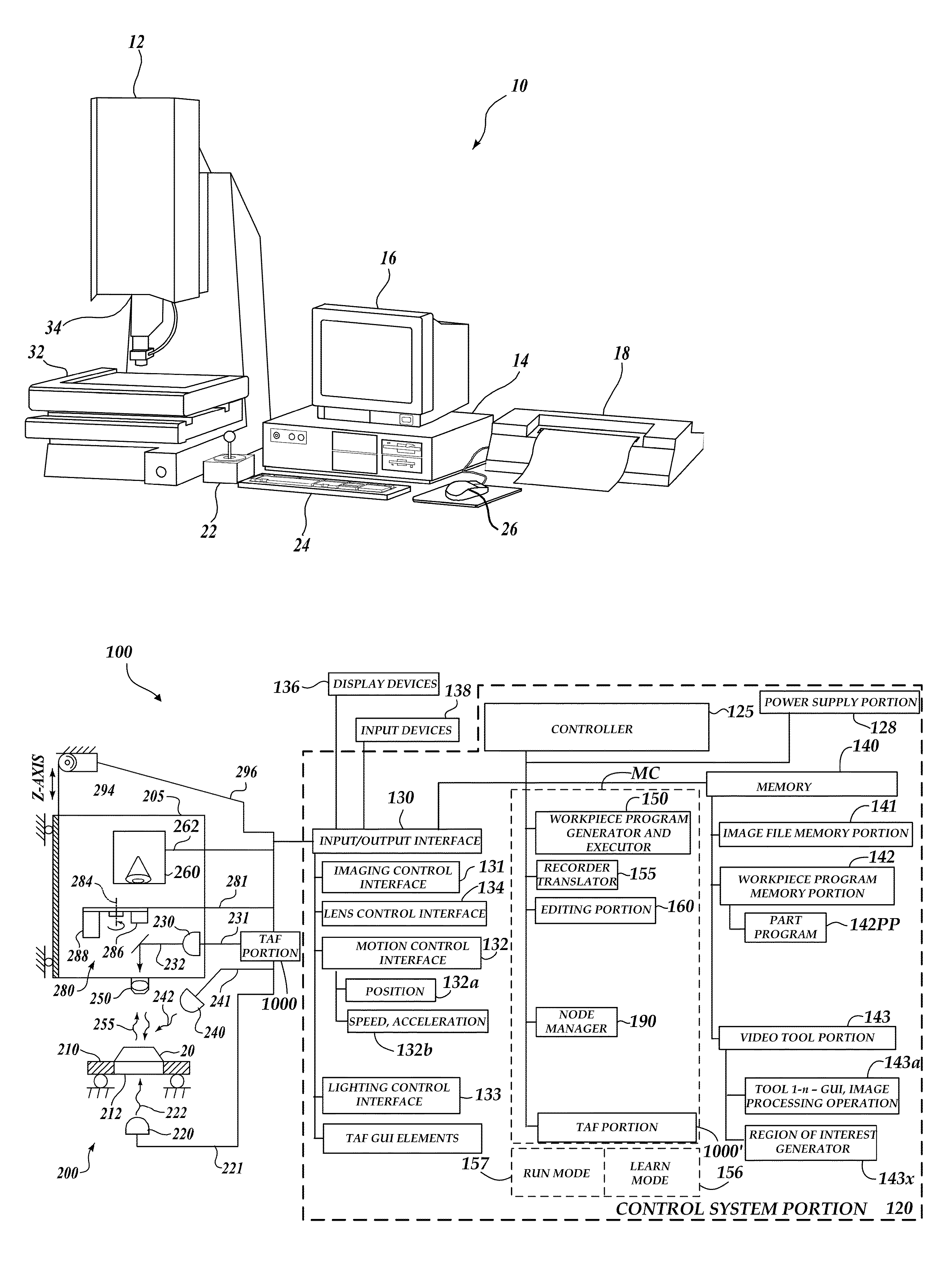
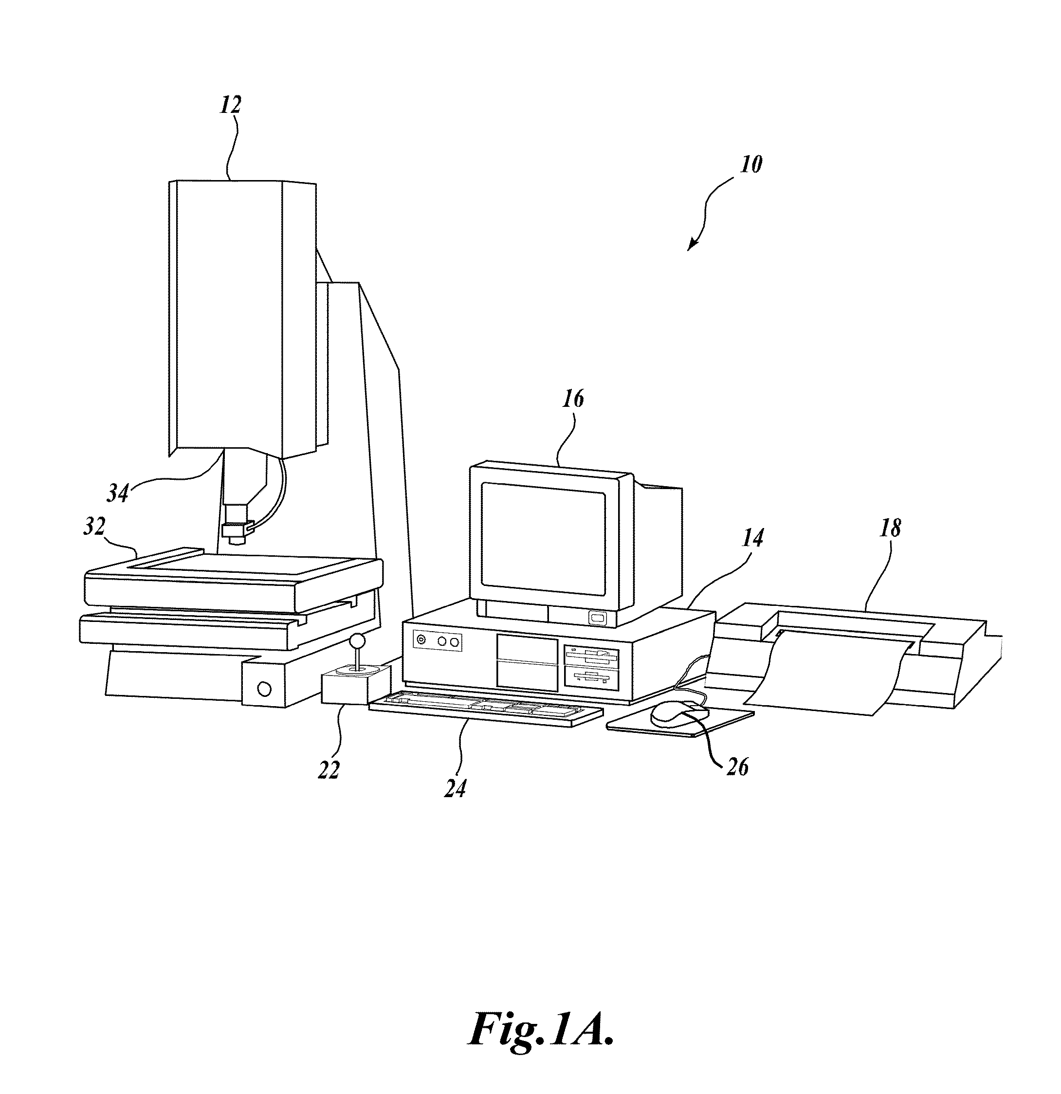
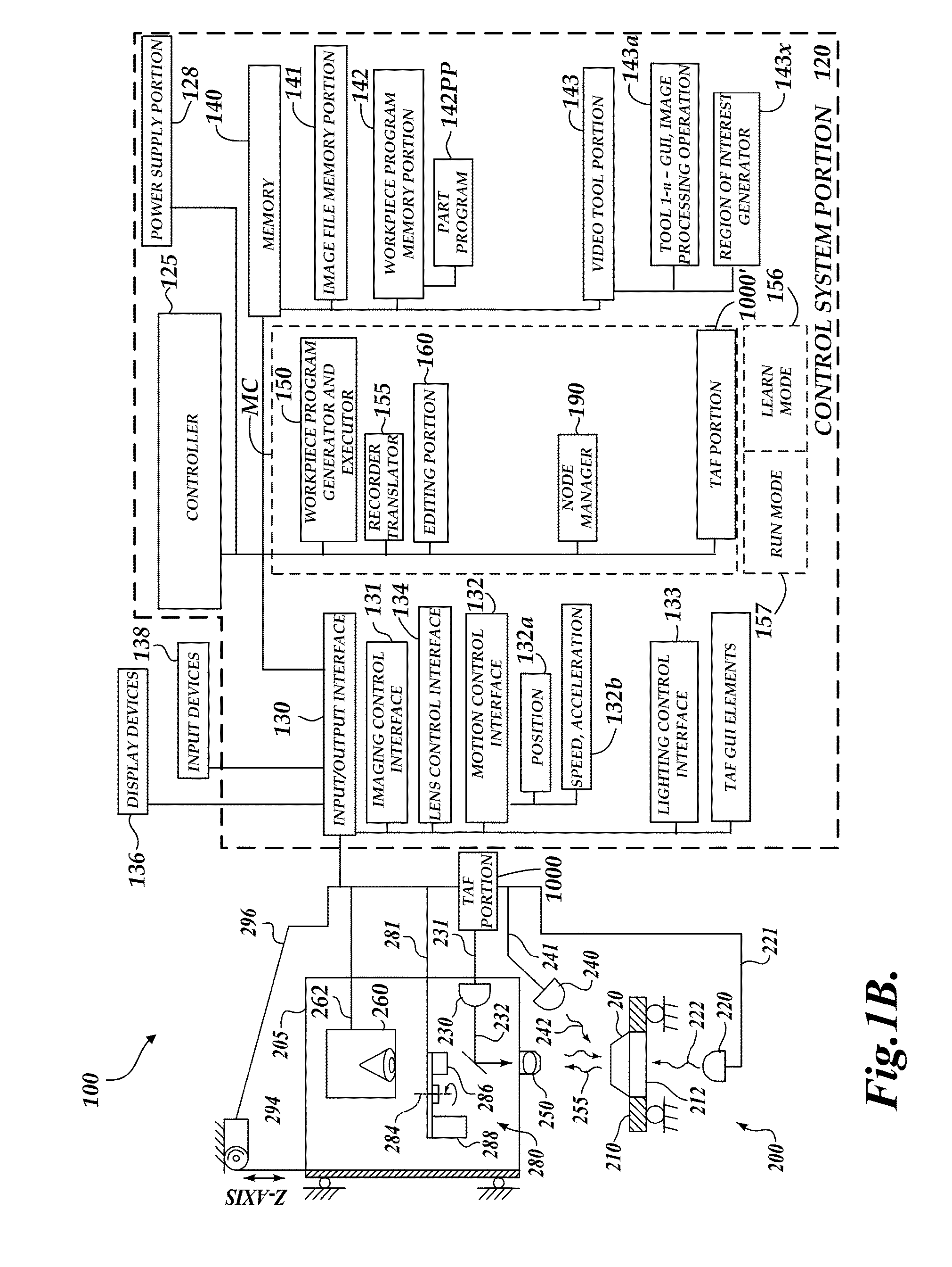
[0022]FIG. 1A is a block diagram of one exemplary machine vision inspection system 10 usable in various embodiments of the present invention. The machine vision inspection system 10 includes a vision measuring machine 12 that is operably connected to exchange data and control signals with a controlling computer system 14. The controlling computer system 14 is further operably connected to exchange data and control signals with a monitor or display 16, a printer 18, a joystick 22, a keyboard 24, and a mouse 26. The monitor or display 16 may display a user interface suitable for controlling and / or programming the operations of the machine vision inspection system 10, such as a GUI for programming and monitoring TAF enable and TAF disable operations in the vision system 10 according to various embodiments of the present invention.

[0023]The vision measuring machine 12 includes a moveable workpiece stage 32, and an optical imaging system 34. The machine vision inspection system 10 is gen...


PUM


Abstract

A method is provided for controlling a Tracking AutoFocus (TAF) portion of a machine vision inspection system including an imaging portion, a movable workpiece stage, a control portion, and graphical user interface (GUI). The TAF portion automatically adjusts a focus position of the imaging portion to focus at a Z height corresponding to a current surface height of the workpiece. The method includes providing the TAF portion, and providing TAF enable and disable operations, wherein: the TAF disable operations comprise a first set of TAF automatic interrupt operations that are automatically triggered by user-initiated operations that include changing the Z height, and the TAF disable operations may further comprise automatic interrupt operations that are automatically triggered based on at least one respective TAF Z height surface tracking characteristic exceeding a previously set TAF disable limit for that respective TAF Z height surface tracking characteristic.

Description

TECHNICAL FIELD[0001]The invention relates generally to machine vision inspection systems, and more particularly to systems and computer-implemented methods for controlling a Tracking AutoFocus (TAF) sensor in a machine vision inspection system.BACKGROUND[0002]Precision machine vision inspection systems (or “vision systems” for short) can be utilized to obtain precise dimensional measurements of inspected objects and to inspect various other object characteristics. Such systems may include a computer, a camera and optical system, and a precision workstage that is movable in multiple directions to allow the camera to scan the features of a workpiece that is being inspected. One exemplary prior art system that is commercially available is the QUICK VISION® series of PC-based vision systems and QVPAK® software available from Mitutoyo America Corporation (MAC), located in Aurora, Ill. The features and operation of the QUICK VISION® series of vision systems and the QVPAK® software are ge...

Claims


Application Information

Patent Timeline
Patent Type & Authority Applications(United States)
IPC IPC(8): H04N5/232G02B21/36
CPCH04N5/23216G02B21/365G02B21/244G01B9/04G01B11/005H04N23/62
Inventor NORTHRUP, RYANYU, DAHAISONOBE, HIRATO
Owner MITUTOYO CORP
Learn More