Inverting apparatus and control method thereof

a technology of inverter and control method, which is applied in the direction of electrical apparatus, ac-dc conversion without reversal, power conversion system, etc., can solve the problems of increasing the impedance of the inverter, generating non-ignorable voltage difference between the two terminals of the feeder, and considerable power generation loss in the renewable energy system. achieve the effect of avoiding power generation losses and effectively maintaining the quality of current generated by the inverter

Inactive Publication Date: 2015-04-16
AU OPTRONICS CORP
View PDF3 Cites 2 Cited by
  • Summary
  • Abstract
  • Description
  • Claims
  • Application Information

AI Technical Summary

Benefits of technology

[0007]One embodiment of present invention is to provide an inverting apparatus and a control method thereof so as to avoid the inverter operating alternatively in either the normal power supply mode or the trip protection mode because of the voltage difference effect caused by the impedance of the feeder. By controlling the control unit to control the output current of the inverter, the output terminal voltage is prevented from increasing and exceeding the alert range so as to avoid that the inverter falls into the trip protection mechanism. When the output terminal voltage increases and falls within the alert range, the control unit will maintain, increase, or reduce the amount of output current received from the renewable energy. As a result, the quality of current generated by the inverter is effectively maintained to avoid the power generation losses of a renewable system.

Problems solved by technology

However, the impedance of the feeder increases with aging and the rising temperature so that the current fed into the feeder generates a non-ignorable voltage difference between the two terminals of the feeder.
However, when the over voltage is caused by the voltage difference effect because of the impedance of the feeder rather than the abnormal condition of mains electricity supply, the inverter usually operates alternatively in either the normal power supply mode or the trip protection mode, thus resulting in considerable power generation losses in a renewable energy system.

Method used


Image

  • Inverting apparatus and control method thereof
  • Inverting apparatus and control method thereof
  • Inverting apparatus and control method thereof

Examples


Embodiment Construction

[0023]Various embodiments are described below to explain this invention. However, these embodiments are not intended to limit the application or methods of the present invention in any specific context. Therefore, descriptions of the embodiments are only intended to illustrate rather than to limit the present invention. It should be noted that, in the following embodiments and attached drawings, elements not directly related to this invention are omitted from depiction, and the dimensional relationships depicted among various elements are only for purposes of illustration, rather than limiting the practical implementation of these elements.

[0024]As used herein, both “couple” and “connect” refer to direct physical contact or electrical contact or indirect physical contact or electrical contact between two or more components. Or they can also refer to reciprocal operations or actions between two or more components.

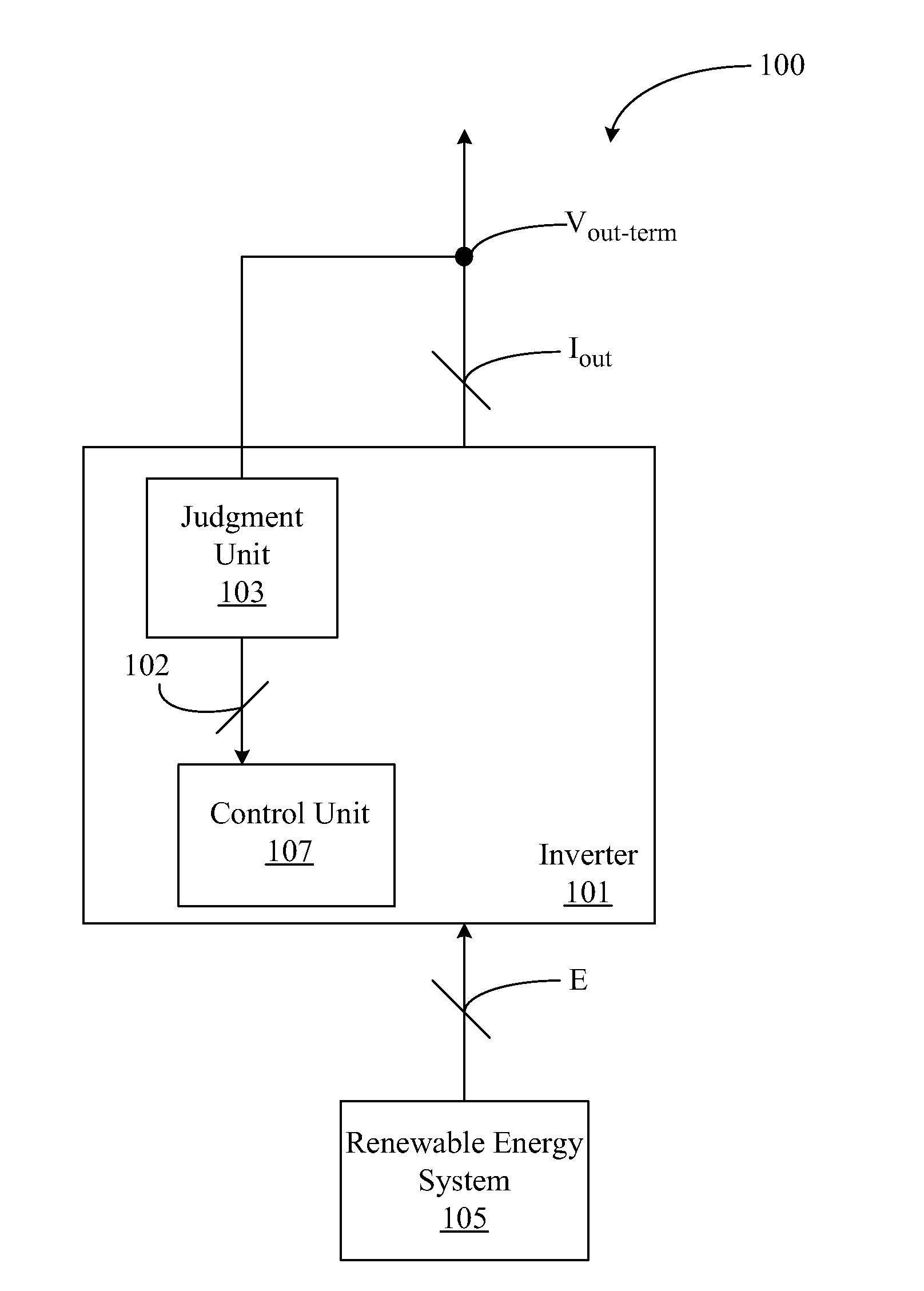
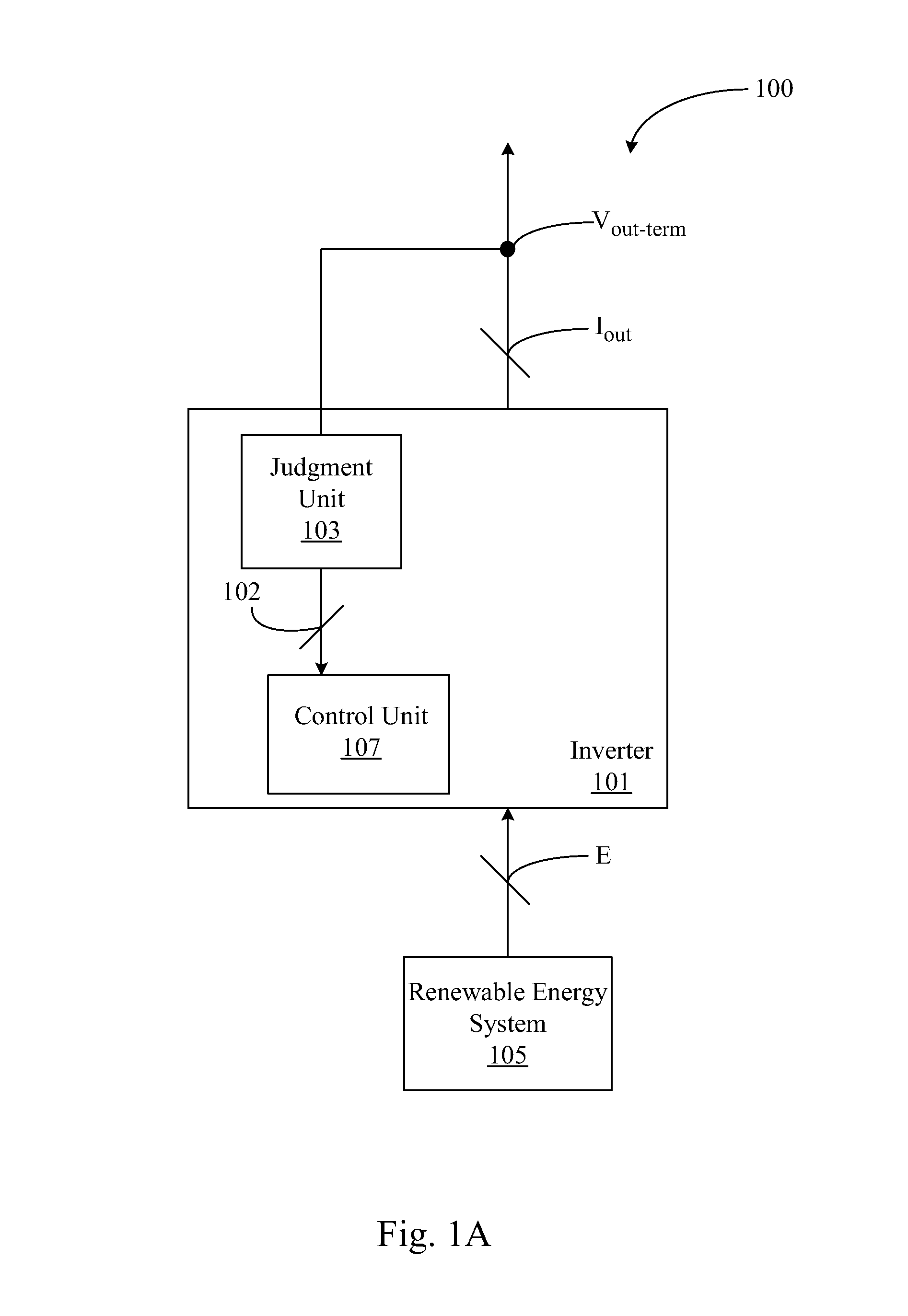
[0025]FIG. 1A depicts a schematic diagram of an inverting apparatus acc...


PUM


Abstract

An inverting apparatus and a control method thereof are disclosed herein. The inverting apparatus includes an inverter. The inverter is configured to convert electrical energy to an output current so as to generate an output terminal voltage. When the output current increases, the output terminal voltage increases correspondingly. The inverter includes a control unit. When the output terminal voltage increases and falls within an alert range, the control unit is configured to control the inverter to decrease the output current or maintain the current output current so as to prevent the output terminal voltage from increasing and exceeding a voltage threshold value that causes the inverter to fall into a trip protection mechanism.

Description

RELATED APPLICATIONS[0001]This application claims priority to Chinese Application Serial Number 201310473976.6, filed Oct. 11, 2013, which is herein incorporated by reference.BACKGROUND[0002]1. Field of Invention[0003]The present invention relates to an inverting apparatus and a control method thereof. More particularly, the present invention relates to an inverting apparatus and a control method thereof for a renewable energy system.[0004]2. Description of Related Art[0005]In recent years, the utilization of renewable energy has gradually become one of the most important technologies in modern society. In order to effectively use renewable energy, an inverter is usually required to convert the electrical energy generated from the renewable energy to an effective alternating current (AC), and then the alternating current is fed into the mains electricity supply through a feeder.[0006]However, the impedance of the feeder increases with aging and the rising temperature so that the cur...

Claims


Application Information

Patent Timeline
Patent Type & Authority Applications(United States)
IPC IPC(8): H02M1/32H02M7/04
CPCH02M1/32H02M7/04
Inventor JEAN, YUAN-BOR
Owner AU OPTRONICS CORP
Why Eureka
Try Eureka