Snow plow

a self-propelled, snow plow technology, applied in snow cleaning, way cleaning, construction, etc., can solve the problems of high inconvenient for workers to make variations, and achieve the effect of reducing the speed gradually, increasing the forward travel speed of the travel device, and increasing the acceleration of the auger

Active Publication Date: 2015-04-23
HONDA MOTOR CO LTD
View PDF3 Cites 12 Cited by
  • Summary
  • Abstract
  • Description
  • Claims
  • Application Information

AI Technical Summary

Benefits of technology

[0010]Thus, the intermediate lowering target angle of inclination is set as an addition to the pre-reversing angle of inclination. Moreover, using the intermediate lowering target angle of inclination as a reference, the speed at which the auger housing is lowered differs between angles greater than and less than this reference. In other words, when the auger housing is above the intermediate lowering target angle of inclination, the auger housing can quickly lower to the intermediate lowering target angle of inclination by lowering at the given lowering speed. When the auger housing is thereafter below the intermediate lowering target angle of inclination, the lowering speed is gradually reduced. As a result, the auger housing can be stopped with precision at the position of the pre-reversing angle of inclination.
[0011]Moreover, the intermediate lowering target angle of inclination is determined from the value of the forward acceleration. A higher forward travel speed of the travel device corresponds to a greater increase in the acceleration of the auger housing. In addressing such circumstances, an increase in acceleration corresponds to a larger additional angle relative to the position of the pre-reversing angle of inclination. As a result, it is possible to prevent the auger housing from going below the pre-reversing angle of inclination due to the effect of its own acceleration.
[0012]Thus, the auger housing can be stopped quickly and precisely at the position of the pre-reversing angle of inclination while the effect of the acceleration of the auger housing as derived from the forward travel speed of the travel device is minimized.

Problems solved by technology

It is highly inconvenient for a worker to make these variations to the height of the auger housing through manual labor.

Method used


Image

  • Snow plow
  • Snow plow
  • Snow plow

Examples


Embodiment Construction

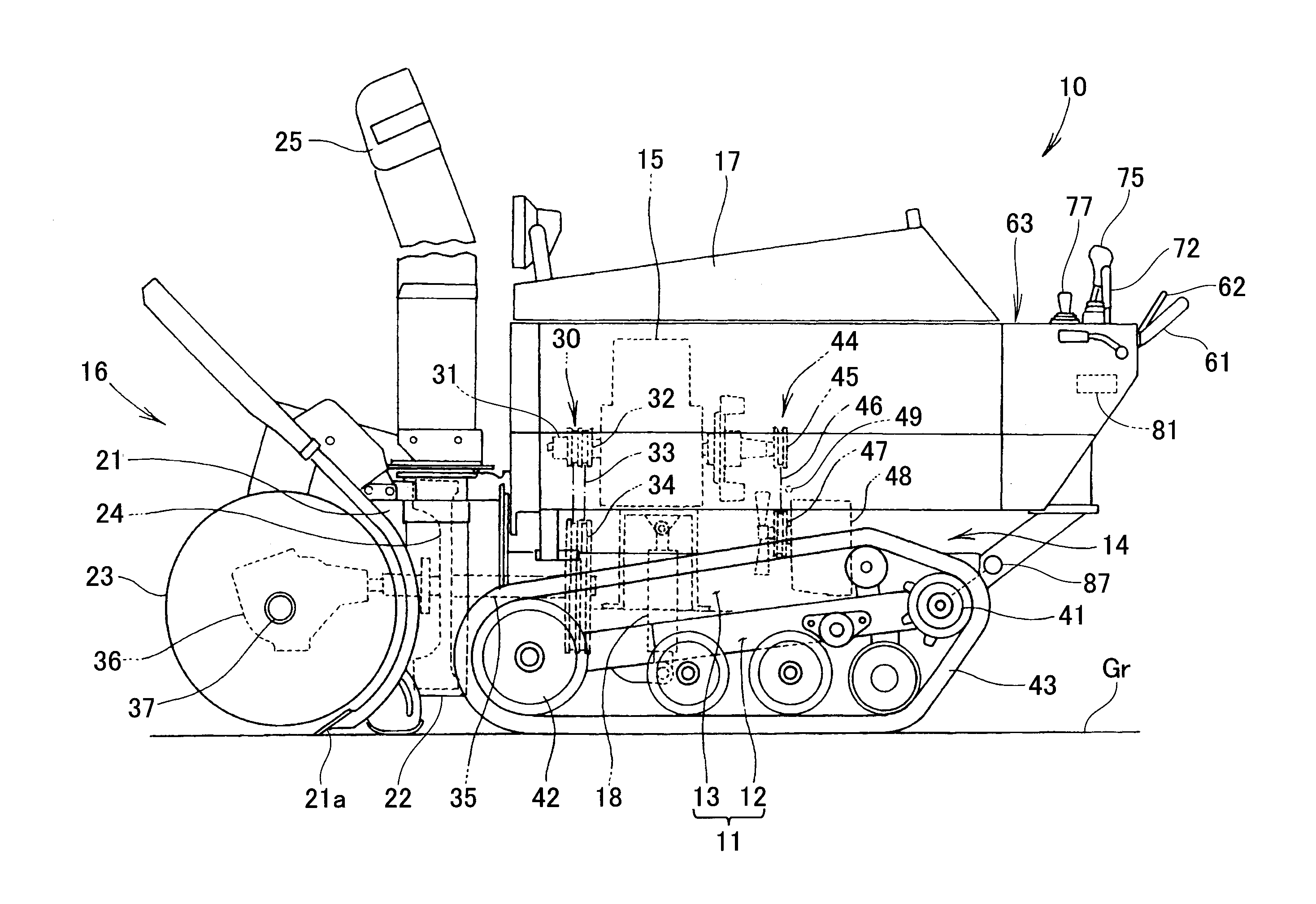
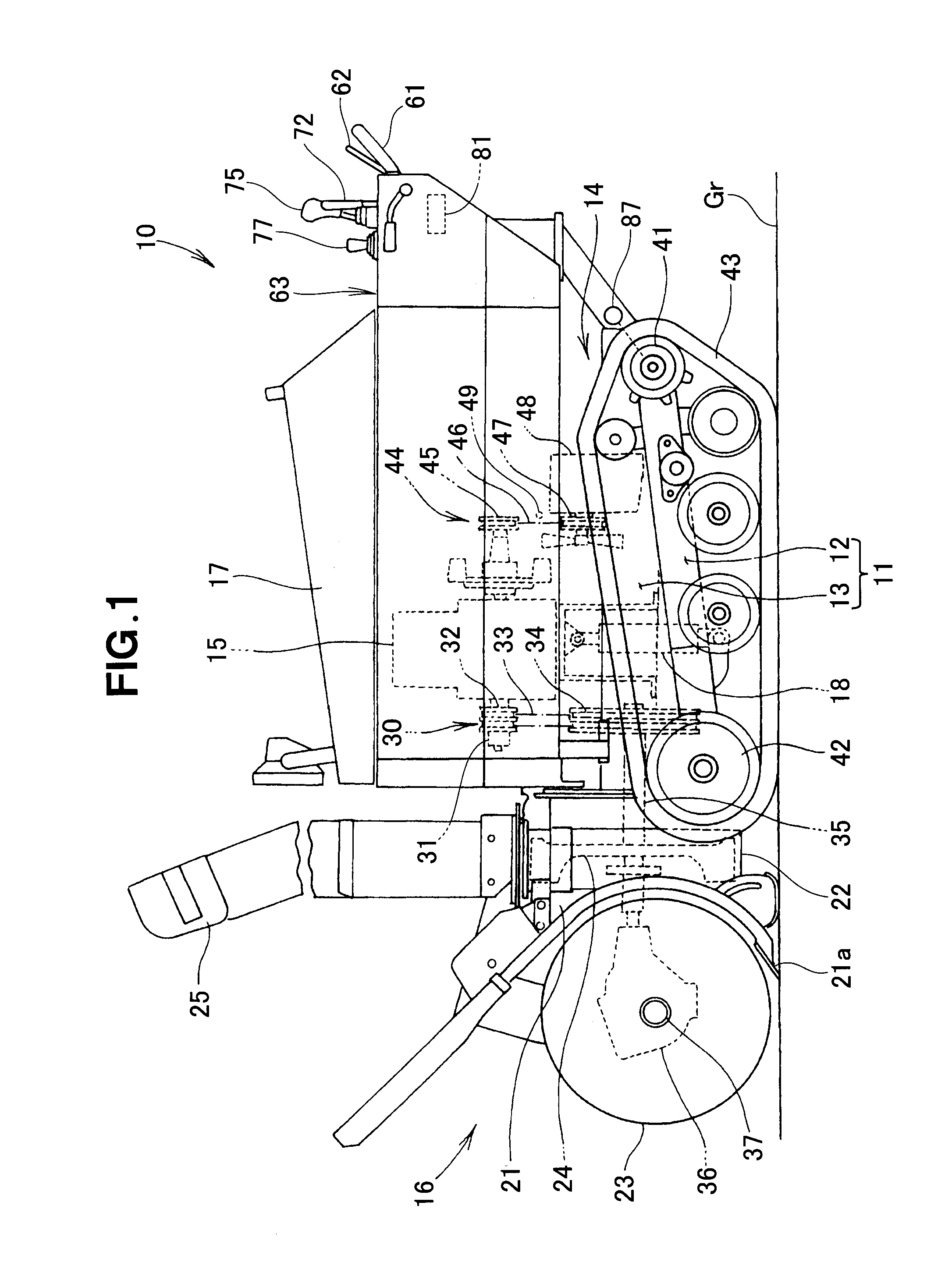
[0023]As shown in FIG. 1, a snow plow 10 is a self-propelled work machine in which an auger 23 and a blower 24 for dispersing snow gathered by the auger 23 peripherally outward from a shooter 25 are driven by an engine 15, the snow plow 10 being self-propelled by means of travel device 14. The engine 15 is covered by an engine cover 17.

[0024]Specifically, a chassis 11 of the snow plow 10 comprises a travel frame 12 and a vehicle body frame 13. The travel frame 12 includes the travel device 14. The vehicle body frame 13 includes the engine 15 and a snow-plowing implement 16. The rear part of the vehicle body frame 13 is mounted to the travel frame 12 so as to be able to swing up and down. The front part of the vehicle body frame 13 is driven by a raising / lowering drive mechanism 18 so as to be raised and lowered (swung up and down).

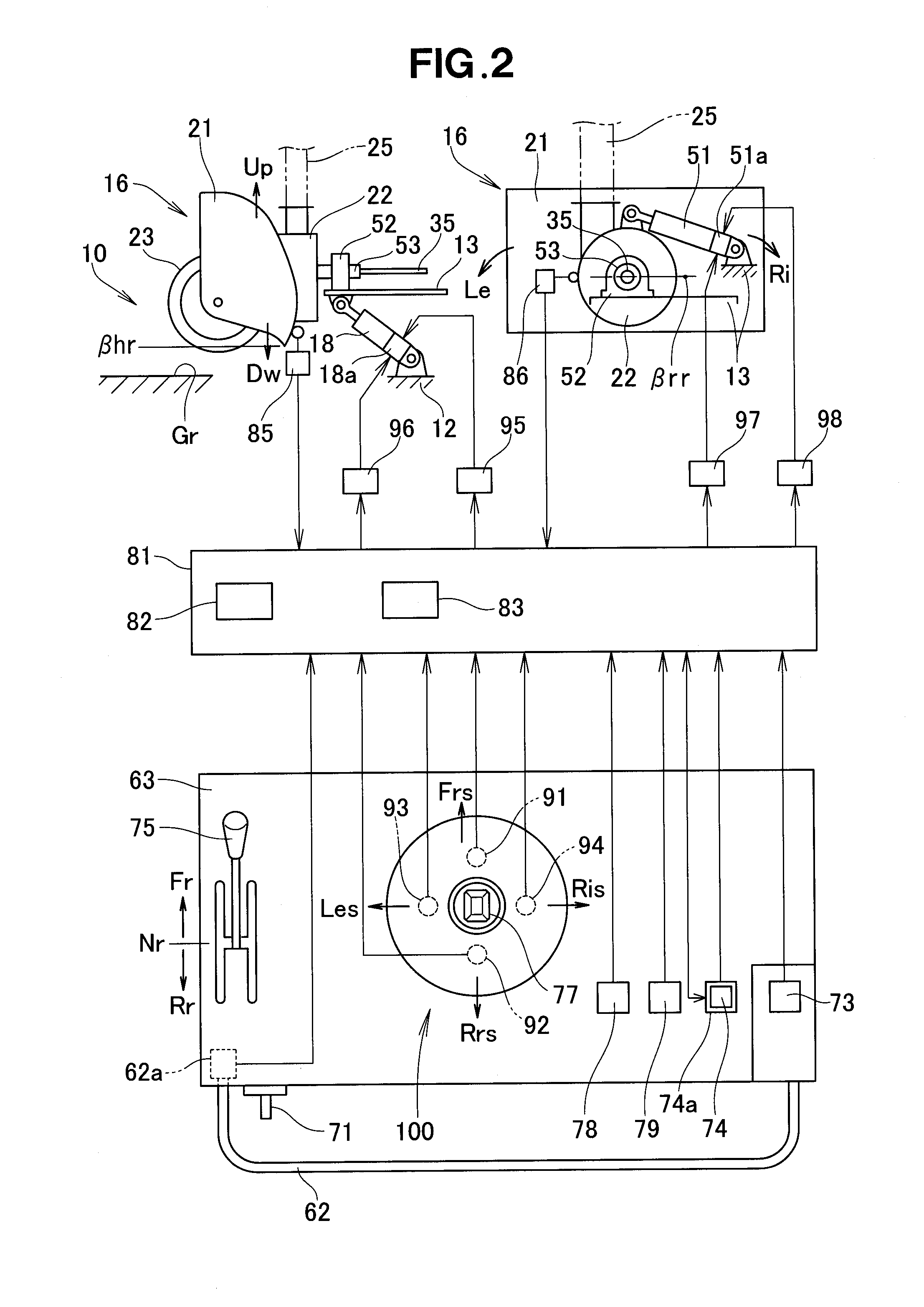
[0025]As shown in FIG. 2, the raising / lowering drive mechanism 18 is an actuator in which a piston can extend from and withdraw into a cylinder. For examp...


PUM


Abstract

A snow plow includes a control unit for raising an auger housing to a predetermined upper limit angle when travel device is reversing, and an acceleration sensor for detecting acceleration produced in the auger housing. The control unit determines an angle of inclination of the auger housing on the basis of the acceleration. When the travel device starts moving forward after having temporarily moved in reverse, the control unit sets an intermediate lowering target angle of inclination, which is in the lowering path of the auger housing from the upper limit angle to a pre-reversing angle of inclination, in accordance with the forward acceleration; lowers the auger housing at a given lowering speed from the upper limit angle to the intermediate lowering target angle of inclination; and lowers the auger housing at a gradually decreasing lowering speed from the intermediate lowering target angle of inclination to the pre-reversing angle of inclination.

Description

FIELD OF THE INVENTION[0001]The present invention relates to a self-propelled snow plow having a travel device and an auger.BACKGROUND OF THE INVENTION[0002]In auger-type snow plows, an auger housing is mounted to a vehicle body frame including travel device, such that the auger housing can be raised and lowered and made to roll. The auger housing includes an auger. An auger snow plow can scrape up snow by means of a front auger while traveling forward, and can disperse the scraped up snow far away by means of a blower via a shooter.[0003]A snow plow including an auger employs a system for varying the height of the auger housing in accordance with the conditions of the snow plowing work. It is more efficient to move the snow plow when the bottom surface of the auger housing has been raised. It is more efficient to plow snow when the bottom surface of the auger housing has been lowered. The height of the auger housing is also often varied according to unevenness in the road surface w...

Claims


Application Information

Patent Timeline
Patent Type & Authority Applications(United States)
IPC IPC(8): E01H5/09
CPCE01H5/098E01H5/04
Inventor FUKANO, JUNMIZOROKE, TSUTOMUNAKAYAMA, SHINSAKU
Owner HONDA MOTOR CO LTD
Why Eureka
Try Eureka