
Monolithic broadband energy collector with dichroic filters and mirrors embedded in waveguide

a technology of dichroic filters and waveguides, applied in the direction of basic electric elements, electromagnetic devices, electrical equipment, etc., to achieve the effect of efficient direct solar energy to the detector

Inactive Publication Date: 2015-04-23
R A MILLIER IND INC
View PDF10 Cites 40 Cited by
  • Summary
  • Abstract
  • Description
  • Claims
  • Application Information

AI Technical Summary

Benefits of technology

In another implementation where multiple reflecting surfaces inside an optical fiber have been used for better utilization of sunlight by collector devices like photovoltaic cells (PV) on both sides of it's structure. This technology helps improve efficiency over traditional methods that use only light rays from outside sources.

Problems solved by technology

The technical problem addressed in this patent text is the efficient integration of a waveguide and a photodetector for high-speed computing and solar energy conversion. The challenge is to achieve high efficiency across a broad spectral band.

Method used


Image

  • Monolithic broadband energy collector with dichroic filters and mirrors embedded in waveguide
  • Monolithic broadband energy collector with dichroic filters and mirrors embedded in waveguide
  • Monolithic broadband energy collector with dichroic filters and mirrors embedded in waveguide

Examples


Embodiment Construction

1. Introduction

[0039]There are many applications for coupling light into a thin optical waveguide. Most techniques for coupling, such as grating coupling and prism coupling, are inherently narrowband due to the dispersion of the waveguide. In the case of prism coupling, the incoming wave typically must be a plane wave, and must also be input at an angle that is commensurate with the effective index of the waveguide, given the prism's inherent dispersion over the spectral band of interest.

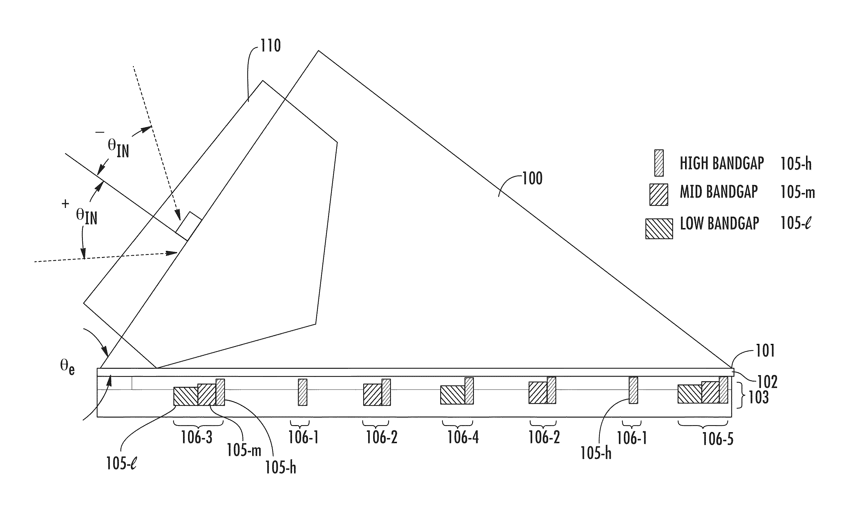
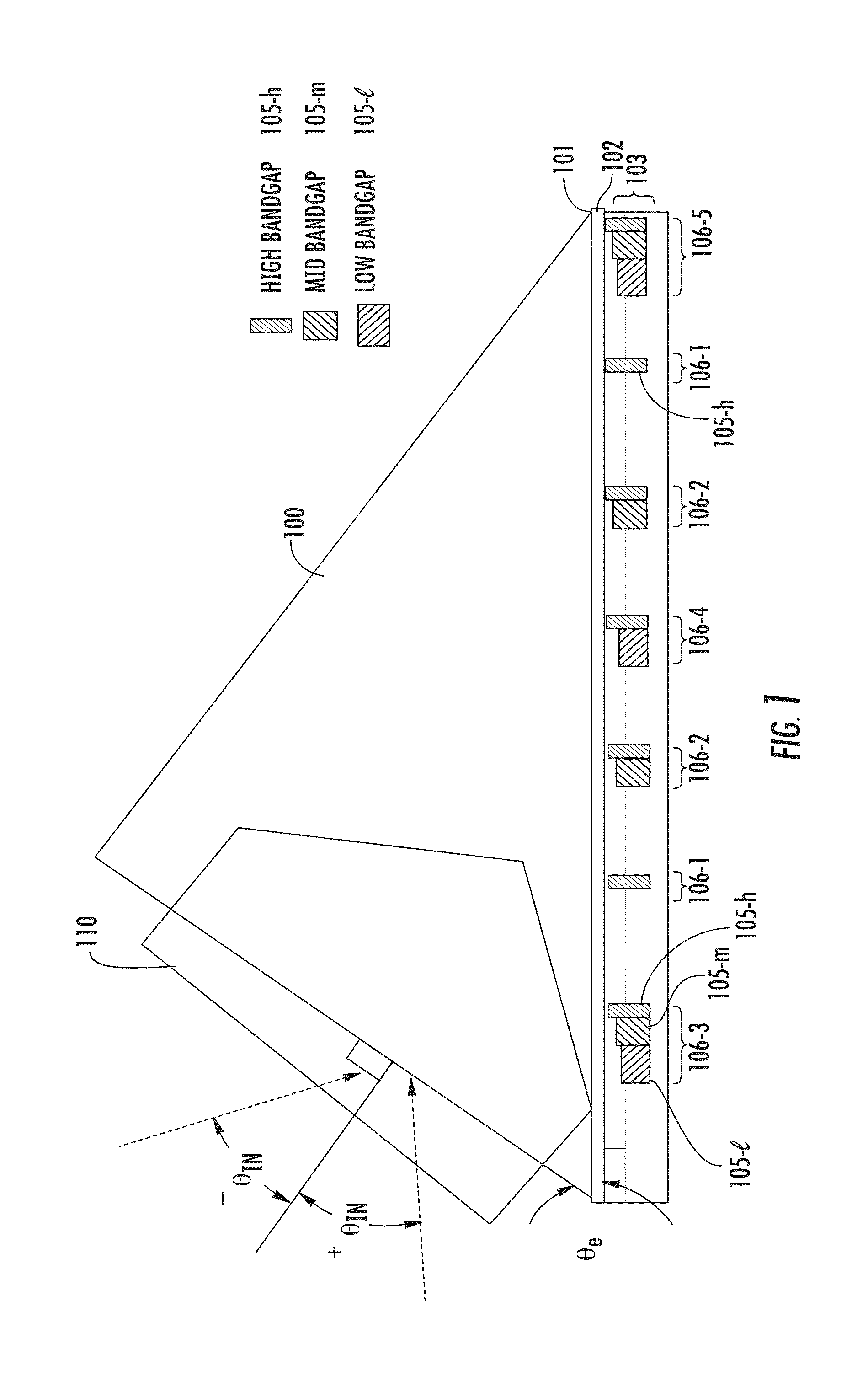
[0040]FIG. 1 is one example of a prism-coupled waveguide approach to a solar collector that improves over other designs. A prism 100 is placed over a waveguide core 102; the waveguide core 102 may also be composed of one or more cladding layers 103 placed on a face of the core 102 opposite the prism 100. The waveguide core 102 has a major axis (the horizontal plane in FIG. 1) aligned with the prism 100. A gap layer 101 is preferably disposed between the prism 100 and the waveguide core 102. One or m...


PUM


Abstract

A solar energy collector includes a planar waveguide formed of multiple material layers having at least two different dielectric constants. Two or more dichroic filters disposed within the waveguide core, and two or more minors are also disposed within the waveguide core. At least one optical to electrical detector positioned in alignment with each of the dichroic filters, and at least one optical to electrical detector is aligned with each of the mirrors. The dichroic filter may be formed from a plurality of material layers.

Description


Claims


Application Information

Patent Timeline
Owner R A MILLIER IND INC
Learn More