Diaphragm and diaphragm valve

a diaphragm valve and diaphragm technology, which is applied in the direction of diaphragm valves, engine diaphragms, operating means/release devices of valves, etc., can solve the problems of no improvement of durability effect, large deformation repeatedly in the diaphragm, and easy cracking around the outer edge of the curved part. , to achieve the effect of excellent durability, excellent durability and excellent durability

Inactive Publication Date: 2015-04-23
FUJIKIN INC
View PDF7 Cites 7 Cited by
  • Summary
  • Abstract
  • Description
  • Claims
  • Application Information

AI Technical Summary

Benefits of technology

[0019]According to the invention of claim 1, the diaphragm is formed in a curved surface shape where the shape before deformation of the lower surface of the membrane part, which deforms and moves up and down with the opening and closing of the flow channel, descends and then ascends from the outer edge part towards the central part, so that an amount of the deformation with the up and down movements of the diaphragm by an opening and closing operation of the diaphragm valve can be reduced, compared with a diaphragm in a curved shape only in the conventional upward or downward direction. Accordingly, even though the opening and closing operation of the diaphragm valve is repeated, a crack is less likely to occur to the diaphragm, thereby obtaining a diaphragm with excellent durability.
[0020]Also, the curve of the diaphragm according to the present invention is smaller compared with the conventional diaphragms. Thus, it becomes easy to place the reinforcing cloth at a substantially intermediate position in a thickness direction so that the reinforcing cloth follows the shape of the diaphragm in molding. Accordingly, a reinforcement effect can be exhibited by the reinforcing cloth, thereby obtaining an improvement effect of excellent durability.
[0021]According to the invention of claim 2, the vertical direction distance between the positions of the uppermost part and the lowest part of the lower surface of the membrane part is a distance of 10% or less to the diameter of the membrane part, so that an amount of the deformation with the up and down movements of the diaphragm by the opening and closing operation of the diaphragm valve can be substantially reduced, thereby obtaining a diaphragm with very excellent durability.
[0022]According to the invention of claim 3, the diaphragm includes a reinforcing cloth at a substantially intermediate position in a thickness direction, so that a reinforcement effect can be sufficiently exhibited by the reinforcing cloth, thereby obtaining a diaphragm with excellent durability.
[0023]According to the invention of claim 4, the reinforcing cloth consists of nylon, so that a high reinforcement effect can be exhibited by the reinforcing cloth, thereby obtaining a diaphragm with very excellent durability.
[0024]According to the invention of claim 5, the surface of the diaphragm is coated in a thin film state with the resin film, so that a reinforcement effect can be exhibited by the resin film, thereby obtaining a diaphragm with excellent durability.

Problems solved by technology

However, such conventional diaphragm in a downwardly or upwardly carved shape deforms largely with up and down movements of the diaphragm by an opening and closing operation of the diaphragm valve.
Therefore, if the opening and closing operation of the diaphragm valve is repeated, large deformation repeatedly occurs in the diaphragm.
Thus, there was a problem that a crack is likely to occur around the outer edge of the curved part which becomes a base end of deformation.
Thus, if the position of the foundation cloth is deviated, sufficient strength cannot be obtained, resulting in no improvement effects of durability.
However, the above-mentioned conventional diaphragm in a downwardly or upwardly carved shape has a large curve, thus there was a difficulty in placing the foundation cloth in a substantially intermediate position in a thickness direction so as to follow the shape of the diaphragm.
In particular, there was a problem that the foundation cloth deviated downwardly from the intermediate position in a thickness direction around the center of the diaphragm.

Method used


Image

  • Diaphragm and diaphragm valve
  • Diaphragm and diaphragm valve
  • Diaphragm and diaphragm valve

Examples


Embodiment Construction

[0033]Hereinafter, suitable embodiments of the diaphragm and the diaphragm valve according to the present invention will be explained with reference to the drawings.

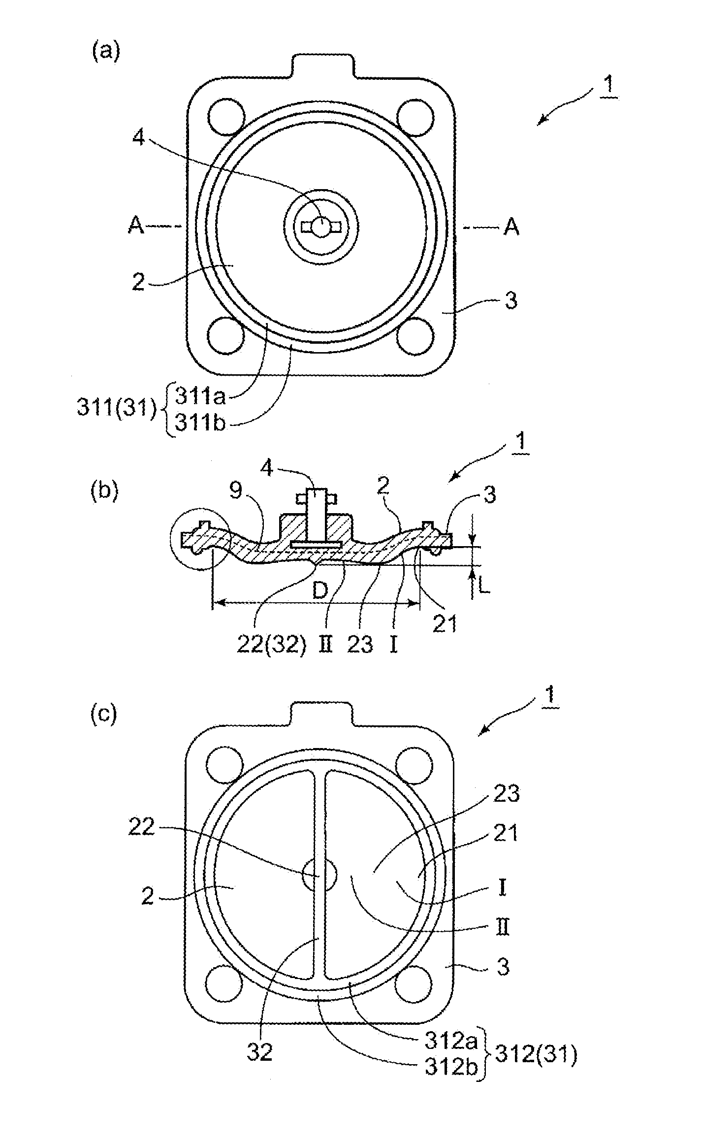
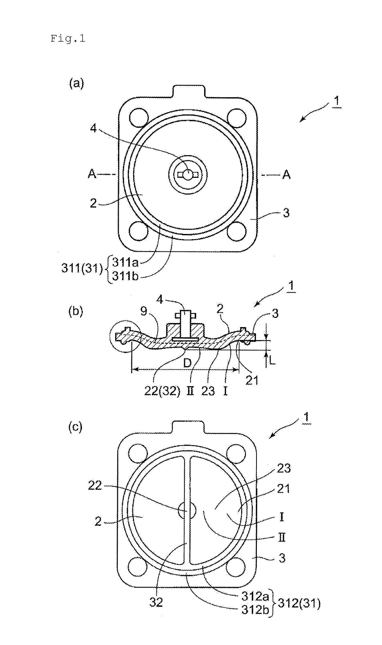
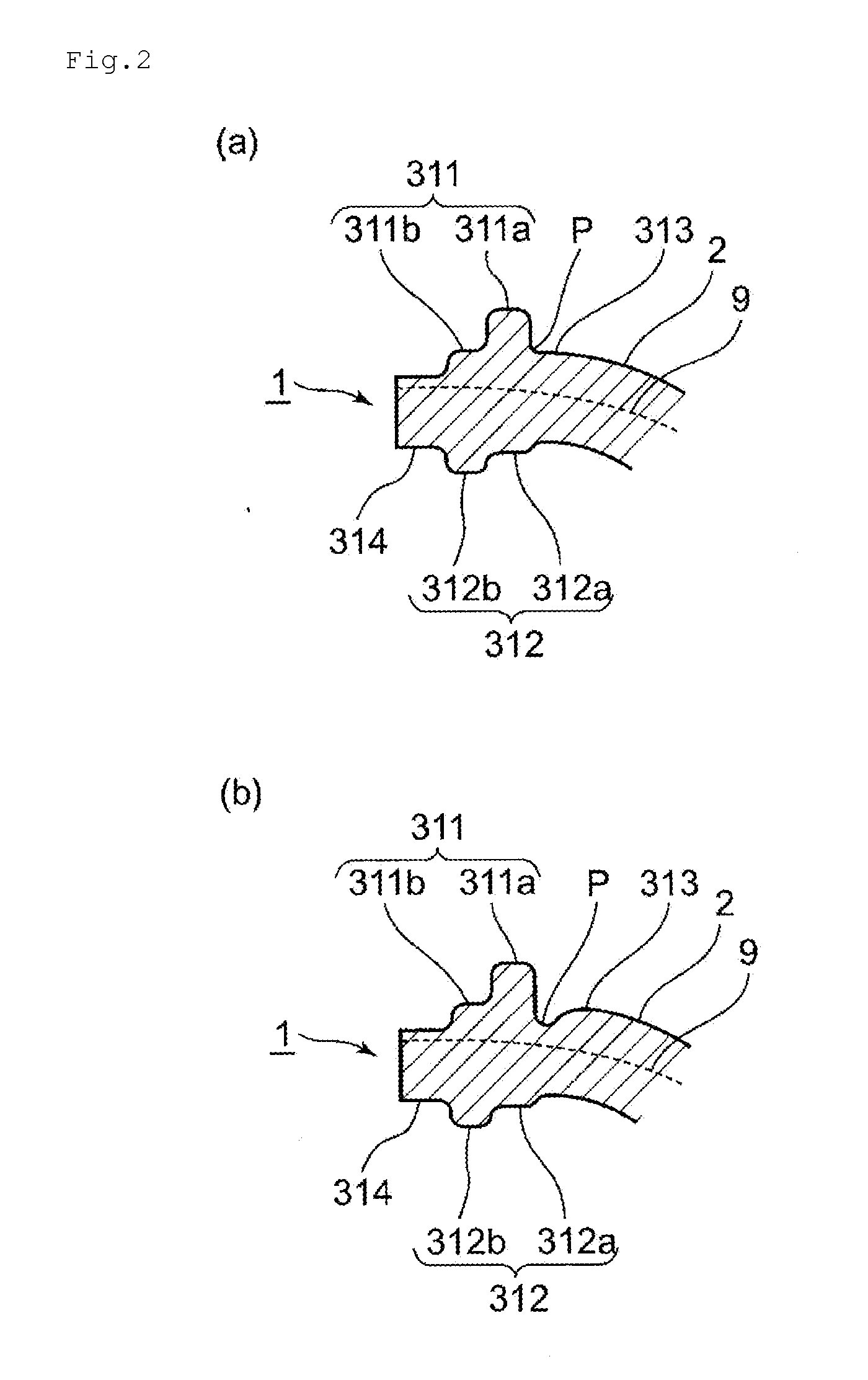
[0034]FIG. 1 shows views illustrating a diaphragm according to the present invention. (a) is a top view, (b) is a sectional view taken along the line A-A of (a), and (c) is a bottom view. FIG. 2 (a) is an enlarged view in the circle of FIG. 1 (b) and (b) shows the change example.

[0035]A diaphragm (1) according to the present invention comprises a membrane part (2) deforming and moving up and down with opening and closing of a flow channel of a diaphragm valve and a flange part (3) which is provided around this membrane part (2) and sandwiched between a valve body and a bonnet of a diaphragm. valve.

[0036]The diaphragm (1) according to the present invention has a feature in a shape before deformation of the membrane part (2).

[0037]“A shape before deformation” is a shape of the membrane part (2) before attaching the diaphra...


PUM


Abstract

A diaphragm with excellent durability is provided which can restrain occurrence of a crack resulting from up and down movements of the diaphragm with opening and closing of a flow channel of a diaphragm valve, and a diaphragm valve having this diaphragm.The diaphragm is attached to a diaphragm valve, comprising a membrane part deforming and moving up and down with opening and closing of a flow channel and a flange part which is provided around said membrane part and sandwiched between a valve body and a bonnet, wherein the diaphragm is formed in a curved surface shape where the shape before deformation of the lower surface of said membrane part descends and then ascends from an outer edge part towards a central part.

Description

TECHNICAL FIELD [0001]The present invention relates to a diaphragm and a diaphragm valve, more particularly a diaphragm with high durability which can restrain of sealing properties and occurrence of a crack resulting from repeated opening and closing of a flow channel of the diaphragm valve, and a diaphragm valve.BACKGROUND OF THE INVENTION [0002]Generally, a diaphragm attached to a diaphragm valve is manufactured by molding materials, such as rubber and resin, in predetermined shape using a metallic mold.[0003]Usually, a molding of a diaphragm is performed in any of a shape of a descended diaphragm (with a flow channel closed) (molding in a closed shape) or a shape of an ascended diaphragm (with a flow channel opened) (molding in an opened shape).[0004]The diaphragm manufactured by the molding in a closed shape is in a downwardly carved shape (for example, see FIG. 19 of the following Patent Document 1), and the diaphragm manufactured by the molding in an opened shape is in an upw...

Claims


Application Information

Patent Timeline
Patent Type & Authority Applications(United States)
IPC IPC(8): F16K7/12
CPCF16K7/12F16J3/02F16K7/126F16K31/1221F16K31/06
Inventor OBARA, SHUNJISHIMOMURA, YOSHINORISOGAO, MASAHIKOKOBAYASHI, KEIGO
Owner FUJIKIN INC
Why Eureka
Try Eureka