
Electric motor assembly and manufacturing method thereof

a technology of electric motors and manufacturing methods, applied in the direction of electrical equipment, dynamo-electric machines, supports/enclosements/casings, etc., can solve the problems of reducing injection pressure, deteriorating stator sealing effect, and deteriorating electric insulation properties, so as to prevent the effect of sealing

Active Publication Date: 2015-04-23
KOBELCO CONSTR MASCH CO LTD
View PDF10 Cites 16 Cited by
  • Summary
  • Abstract
  • Description
  • Claims
  • Application Information

AI Technical Summary

Benefits of technology

The technical effect of this patent is to provide an electric motor assembly and method of manufacture that prevents sealant from leaking through the wires during the process of manufacturing the electric motor.

Problems solved by technology

The leakage of sealant reduces the injection pressure to deteriorate the stator sealing effect.
Besides, the leaked sealant may intrude into the terminal block to deteriorate the electric insulation property.

Method used


Image

  • Electric motor assembly and manufacturing method thereof
  • Electric motor assembly and manufacturing method thereof
  • Electric motor assembly and manufacturing method thereof

Examples


Embodiment Construction

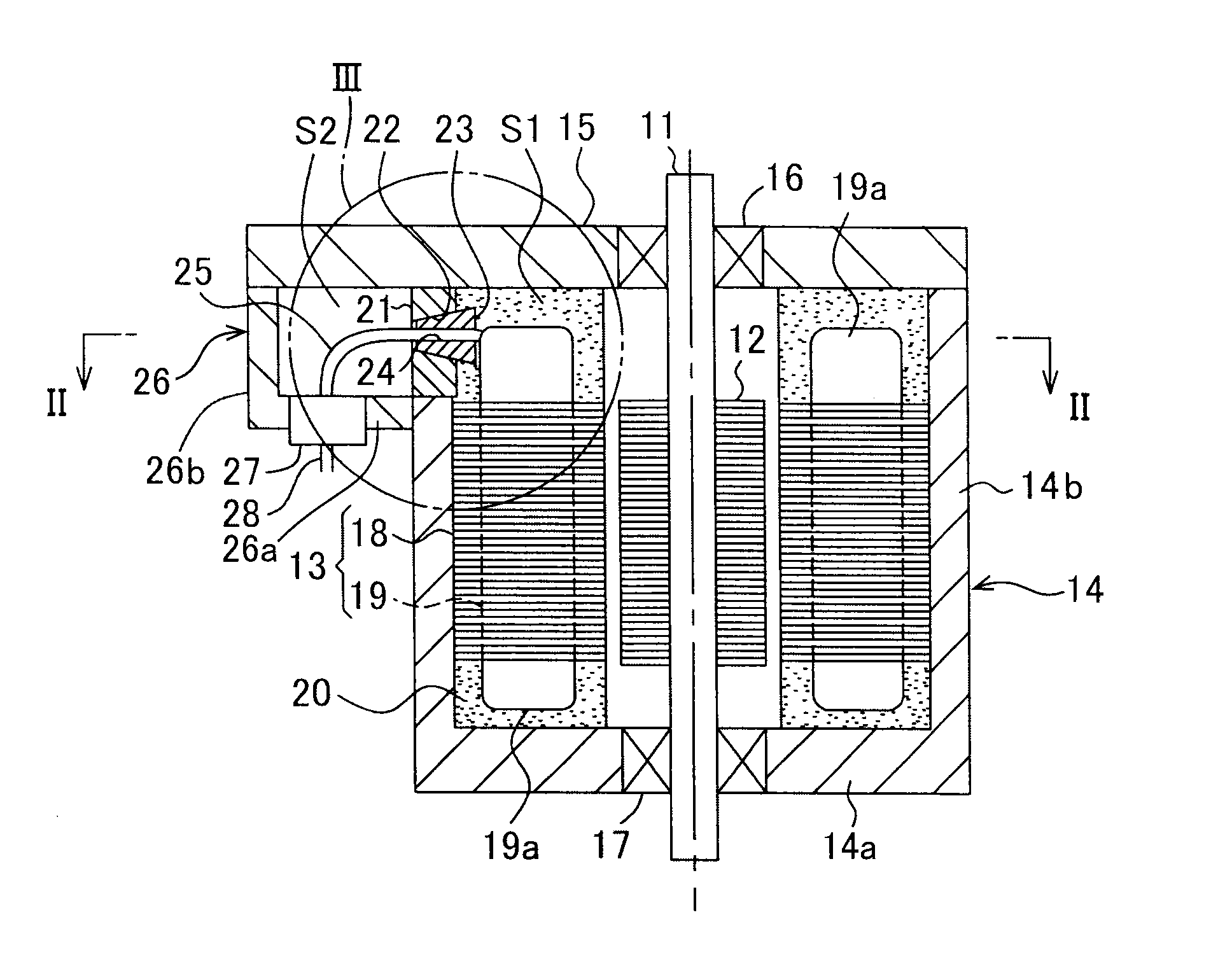
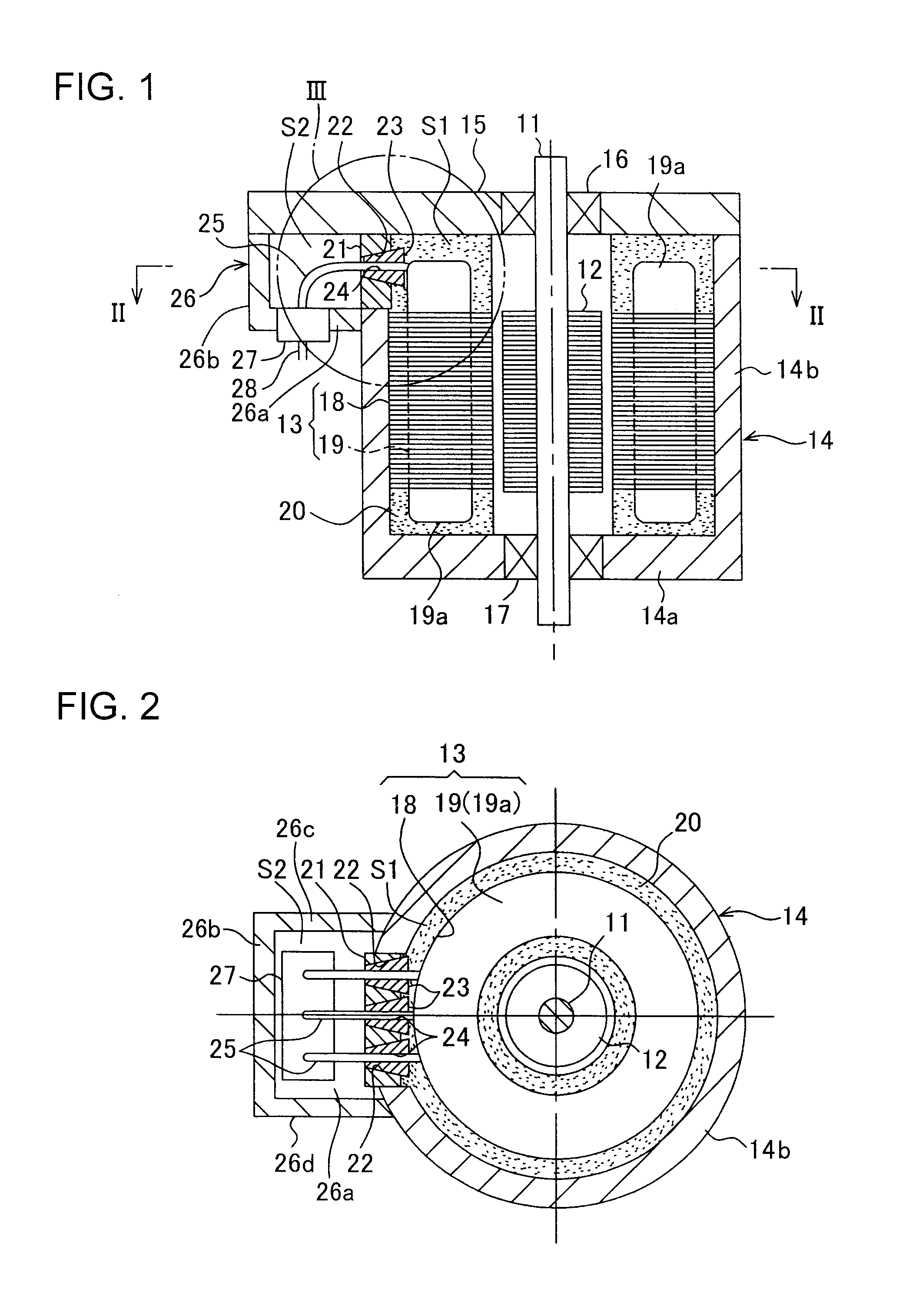
[0020]Described are embodiments of the invention with reference to FIG. 1 to FIG. 5. The embodiments relates to an electric motor installed in a vertical posture like the electric motor illustrated in FIG. 6.

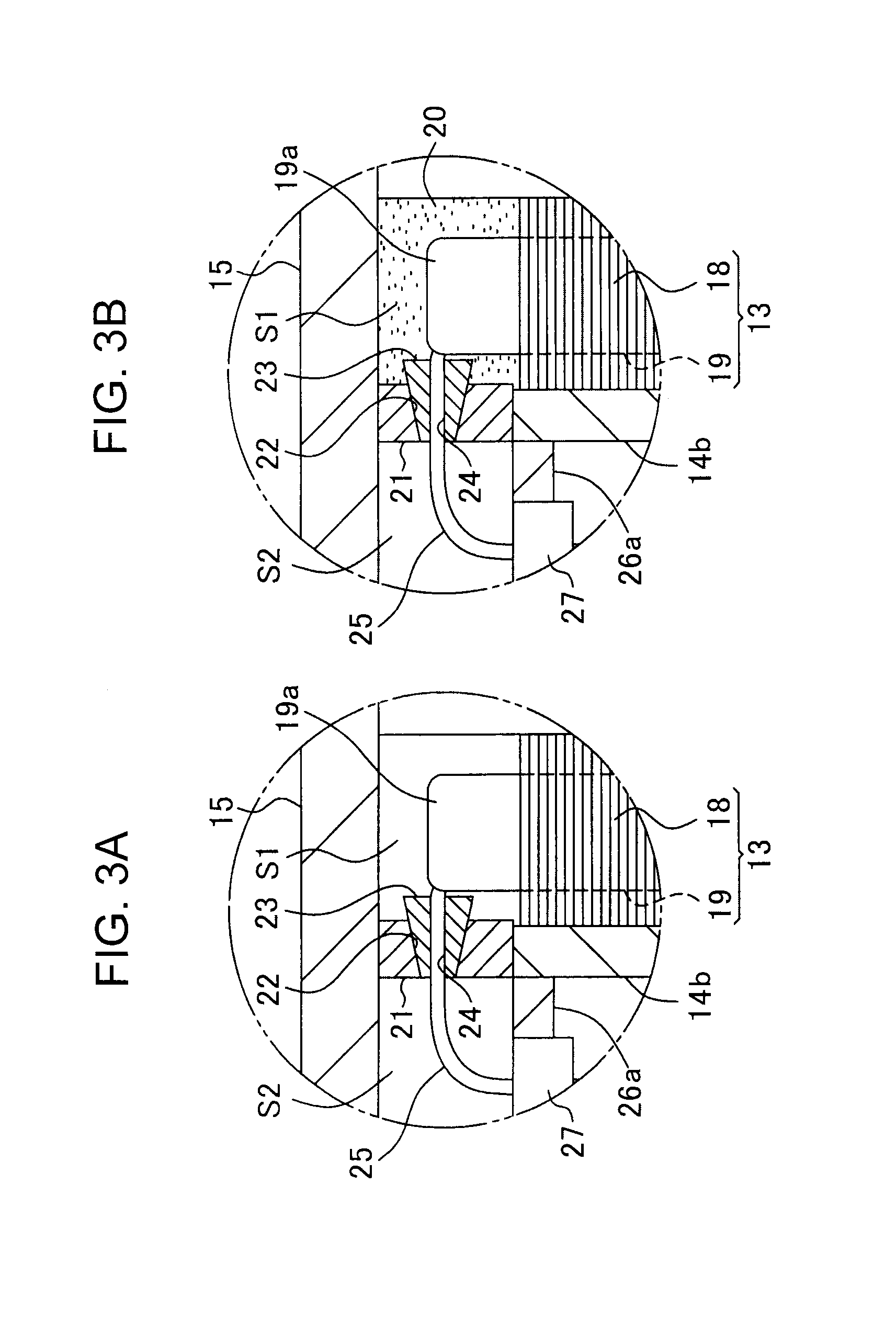
[0021]Specifically, the electric motor according to each of the embodiments is manufactured by injecting a sealant 10 into an electric motor assembly. The electric motor assembly includes an electric motor shaft 11, a rotor 12 which is rotated about the electric motor shaft 11, a stator 13 disposed around the rotor 12, a casing 14 which accommodates the rotor 12 and the stator 13, and a cover 15 to be mounted on one axial end of the casing 14. The casing 14 includes a bottom wall 14a and a peripheral wall 14b located on the upper side of the bottom wall 14a and joined to the perimeter of the bottom wall 14a. The cover 15 is mounted on the upper end surface of the casing 14 by not-graphically-shown bolts. The upper and lower portions of the electric motor shaft 11 are rotatably s...


PUM


Abstract

Provided are, an electric motor assembly capable of preventing a sealant from leakage through a lead-wire drawing portion, and an electric motor manufacturing method with use of the electric motor assembly. The electric motor assembly includes a rotor (12), a stator (13), a casing (14), a partition wall (21) with through-holes (22), plugs (23) made of a highly elastic material and including a tapered outer peripheral surface to be fitted into the through-holes (22), and lead wires (25) connected to the stator (13). The plugs (23) surround lead-wire insertion holes (24). A sealant (20) is injected into the casing (14) in a state that the lead wires (25) are drawn through the lead-wire insertion holes (24). The injection pressure presses the plugs (23) outwardly to bring the outer peripheral surfaces of the plugs (23) into close contact with the inner peripheral surface surrounding the through-holes (22) and elastically deforms the plugs (23) in a diameter-reduction direction to cause the plugs (23) to close the lead-wire insertion holes (24).

Description

TECHNICAL FIELD[0001]The present invention relates to an electric motor assembly provided with a stator including coil ends and allowed to be molded with a sealant so as to entirely or partially seal the stator, and to an electric motor manufacturing method with use of the electric motor assembly.BACKGROUND ART[0002]FIG. 6 illustrates a conventional electric motor. The electric motor includes an electric motor shaft 1, a rotor 2 which is rotated about the electric motor shaft 1, a stator 3 disposed around the rotor 2, a casing 4 which accommodates the rotor 2 and the stator 3, and a cover 5 to be mounted on one axial end of the casing 4. The electric motor is installed in such a vertical posture that the electric motor shaft 1 extends vertically, such as a slewing electric motor for an excavator. In the following, the conventional art shown in FIG. 6 and the embodiments of the invention to be described later are explained based on the premise that the electric motor is installed in ...

Claims


Application Information

Patent Timeline
Patent Type & Authority Applications(United States)
IPC IPC(8): H02K3/44
CPCH02K3/44H02K3/32H02K3/38H02K5/08H02K5/10H02K5/225H02K15/105H02K15/12
Inventor NAKAZUMI, AKIRASAIKI, SEIJIKOIWAI, KAZUSHIGEKARATA, YOSHIKIYAMAZAKI, YOICHIRO
Owner KOBELCO CONSTR MASCH CO LTD
Learn More