In-vehicle camera

a technology for in-vehicle cameras and cameras, which is applied in the field of in-vehicle cameras, can solve the problems of in-vehicle camera body not being completely fixed to the windshield, windshield scratches, and windshield slipping from the vehicl

Active Publication Date: 2015-04-23
DENSO CORP
View PDF7 Cites 49 Cited by
  • Summary
  • Abstract
  • Description
  • Claims
  • Application Information

AI Technical Summary

Benefits of technology

The in-vehicle camera can be attached to the windshield without damaging the windshield or causing any looseness in the camera. It uses a bracket that is pressed against the windshield or the hook, ensuring a secure attachment without any movement between the camera and the bracket. This design prevents the windshield from coming off the vehicle or getting scratches. Overall, the in-vehicle camera can be reliably attached to the windshield with no additional tools or assembly steps.

Problems solved by technology

Therefore, when the bracket is pushed strongly such as by a jig in mounting the in-vehicle camera to the bracket, the windshield may come off from the vehicle, or the windshield may be scratched by the jig.
The problem is that, since tolerances are set to the button and the hook respectively, the in-vehicle camera body is not completely fixed to the windshield.
In the case of an in-vehicle camera for monitoring the conditions ahead of the vehicle, a possible occurrence of looseness due to the tolerances leads to a problem of disabling correct monitoring of the conditions ahead of the vehicle.
In this case, the occurrence of looseness in the in-vehicle camera leads to a problem that the grasped positional relationship is incorrect accordingly.

Method used


Image

  • In-vehicle camera
  • In-vehicle camera
  • In-vehicle camera

Examples


Embodiment Construction

[0030]With reference to the drawings, hereinafter is described an embodiment of the present invention.

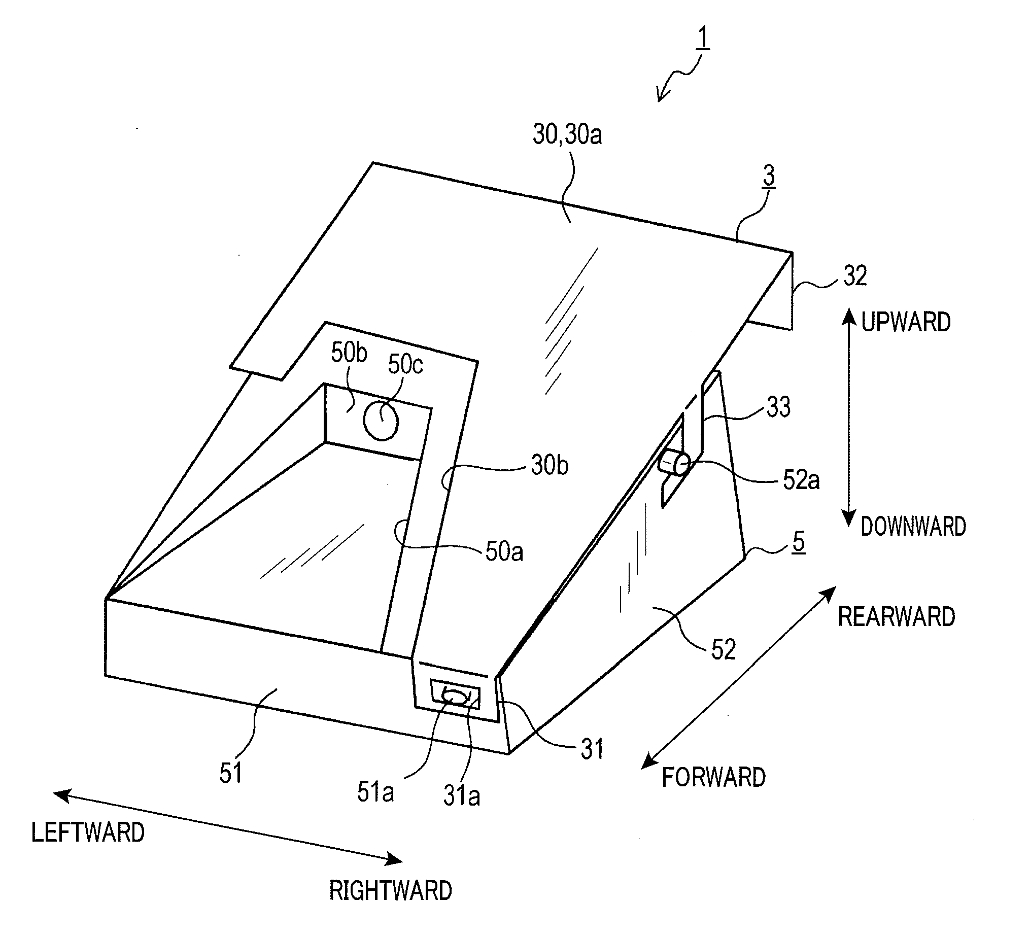
[0031]An in-vehicle camera of the present invention is used for imaging and monitoring the conditions ahead of the vehicle. In the following description, a forward direction is defined to be a direction to which the in-vehicle camera is oriented in a state where the in-vehicle camera is correctly mounted to the windshield of the vehicle at a predetermined position thereon to image the conditions ahead of the vehicle.

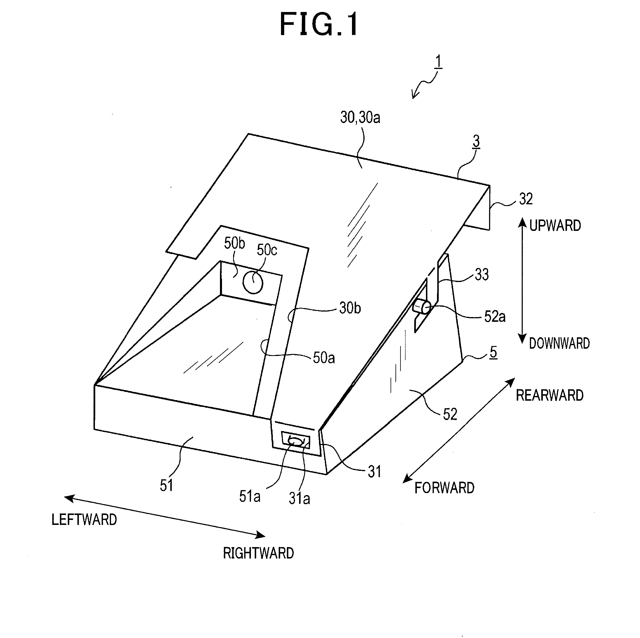
[0032]Further, the terms rearward, rightward, leftward, upward and downward used in the following description are the directions based on triangular projection with the forward direction relative to the vehicle being a front (indicated by arrows in FIG. 1), and thus the description referring such as to plan views or rear views is also based on triangular projection. General structure As shown in FIG. 1, an in-vehicle camera 1 of the present embodiment includes a bracket ...


PUM


Abstract

In an in-vehicle camera 1, when an in-vehicle camera body 5 is hooked on a hook portion 33 of a bracket 3 attached to a windshield, a leaf spring 34 presses the in-vehicle camera body 5 against the bracket 3 to fix the in-vehicle camera body to the bracket 3. Therefore, the in-vehicle camera body 5 can be attached to the windshield without permitting the windshield to come off from the vehicle by the bracket's being strongly pushed such as by a jig, or without permitting the jig to scratch the windshield. Since the in-vehicle camera body is fixed to the bracket 3 by being pressed against the bracket 3 by the leaf spring 34, there is no problem of causing backlash relative to the bracket 3.

Description

CROSS-REFERENCE TO RELATED APPLICATIONS[0001]This application is a U.S. National Phase Application under 35 U.S.C. 371 of International Application No. PCT / JP2013 / 055631 filed on Mar. 1, 2013 and published in Japanese as WO 201 3 / 1 41 000 A1 on Sep. 26, 2013. This application is based on and claims the benefit of priority from Japanese Patent Application No. 2012-062350 filed Mar. 19, 2012. The entire disclosures of all of the above applications are incorporated herein by reference.BACKGROUND OF THE INVENTION[0002]1. Technical Field[0003]The present invention relates to an in-vehicle camera that is attached to a windshield from inside the vehicle.[0004]2. Background Art[0005]An in-vehicle camera that monitors the conditions ahead of the vehicle includes a bracket attached to a windshield and an in-vehicle camera body fixed to the bracket.[0006]Such an in-vehicle camera is attached to the windshield in the course of manufacturing the vehicle. Specifically, in the manufacture, the bra...

Claims


Application Information

Patent Timeline
IPC IPC(8): B60R11/04
CPCB60R2011/0026B60R11/04
Inventor OKUDA, SYO
Owner DENSO CORP
Why Eureka
Try Eureka