Contact protection system for power busbars

Active Publication Date: 2015-04-23
WOHNER GMBH & CO KG ELEKTROTECHNISCHE SYST
View PDF12 Cites 20 Cited by
  • Summary
  • Abstract
  • Description
  • Claims
  • Application Information

AI Technical Summary

Benefits of technology

[0030]This offers the advantage that the contact protection modules can be attached to the power busbars in a particularly simple and convenient manner.
[0031]In the case of a further possible embodiment of the contact protection system in accordance with the invention, an edge profile can be inserted at a lower edge

Problems solved by technology

One disadvantage of these conventional power busbar systems thus resides in the fact that mounting or removal of devices is only possible if the power busbar system is completely switched off.
Therefore, in the case of these conventional systems it is not possible to supply current continuously to all of the connected devices, as when a device is replaced current can no longer be supplied to the remaining electrical devices by the power busbar system by reason of the required switch-off procedure.
This is a major disadvantage in particular in certain applications, e.g. in the case of current supply systems of hospitals or the like, as in many situations current must always be supplied to certa

Method used


Image

  • Contact protection system for power busbars
  • Contact protection system for power busbars
  • Contact protection system for power busbars

Examples


Embodiment Construction

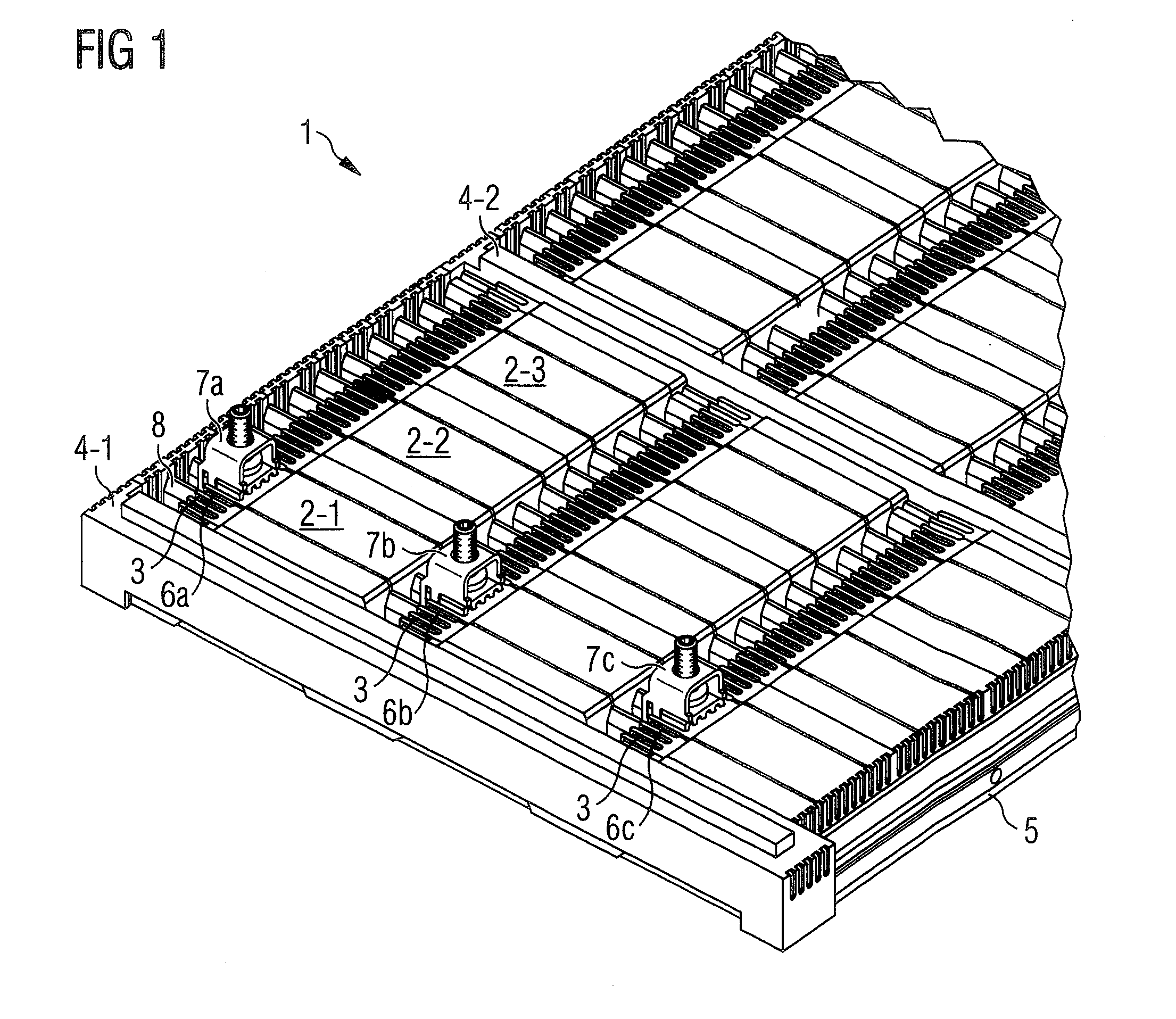
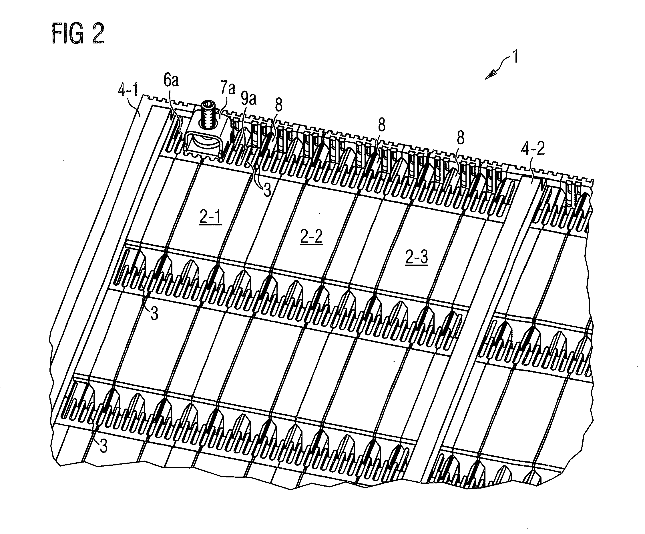
[0053]As can be seen in FIG. 1, the inventive contact protection system 1 for power busbars 9 is constructed in a modular manner. A plurality of contact protection modules 2, which each comprise holding feet for engaging behind the power busbars 9, are mutually latched to adjacent contact protection modules 2 with the aid of latching elements and cover the power busbars 9 (not visible in FIG. 1) in a planar manner. The planar contact protection modules 2 illustrated in FIG. 1 can be attached to, or slid onto, the power busbars 9 preferably with the aid of the holding feet. Therefore, the contact protection modules 2 can be attached to the power busbars 9 in a simple manner. Each of the contact protection modules 2-i comprises for each power busbar 9 a terminal-receiving region 6 for receiving connecting terminals 7, wherein the connecting terminals 7 are provided for electrically contacting the power busbars 9 located underneath the contact protection modules 2. In the case of the e...


PUM


Abstract

Contact protection system for power busbars having planar contact protection modules which each comprise holding feet for engaging behind the power busbars and latching elements for mutually latching with adjacent contact protection module, wherein the contact protection modules comprise for each power busbar a terminal-receiving region for receiving connecting terminals which are provided for electrically contacting the respective power busbar.

Description

BACKGROUND[0001]The invention relates to a contact protection system for power busbars which serve to supply electric current to switching devices.[0002]Busbars, in particular power busbars, comprise an arrangement of conductors which can be used for distributing electric energy. Busbars are manufactured from aluminium or copper and are generally uninsulated so as to simplify connection and switching elements. Therefore, the contact protection is typically ensured by means of a housing of the switching system.[0003]After the housing is opened, conventional busbars do not offer any contact protection, which means that busbar systems are generally only found in main distribution boards, in which extensive safety measures mean that the access is restricted to correspondingly qualified, electrically skilled personnel.SUMMARY OF THE INVENTION[0004]One or a plurality of electrical devices, in particular switching devices, can be mounted on the power busbars. In many cases, the accessible ...

Claims


Application Information

Patent Timeline
IPC IPC(8): H02H7/22
CPCH02H7/22H01R13/512H01R13/629H02B1/14H02B1/20H02B1/043H02B1/0565H02B1/06Y10S439/949H02G5/00H01R9/2675H02B1/044H02G5/04
Inventor BUETTNER, ALEXSTEINBERGER, PHILIPPMASEL, JORAMLEISTNER, FRANK
Owner WOHNER GMBH & CO KG ELEKTROTECHNISCHE SYST
Why Eureka
Try Eureka