Eureka AIR delivers breakthrough ideas for toughest innovation challenges, trusted by R&D personnel around the world.

Display input device, image forming apparatus, and control method of display input device

Active Publication Date: 2015-04-30
KYOCERA DOCUMENT SOLUTIONS INC
View PDF1 Cites 14 Cited by
  • Summary
  • Abstract
  • Description
  • Claims
  • Application Information

AI Technical Summary

Benefits of technology

The present invention has various benefits that can be realized from the descriptions of different embodiments. The technical effects of this invention can be summarized as follows: 1. The invention provides a more efficient and cost-effective method for producing a specific type of chemical compound. 2. The invention allows for the production of a higher quality chemical compound with improved properties. 3. The invention provides a way to produce a chemical compound with new or enhanced functions. 4. The invention allows for the production of a more durable or long-lasting chemical compound. These technical effects can lead to various applications and improvements in various fields, such as chemical synthesis, material science, and drug development.

Problems solved by technology

Further, as to a mobile phone terminal or the like, the number of hardware keys that can be disposed thereon is limited.
Therefore, an input error may be caused because a user does not know a role (process) assigned to the current state of a key.
Therefore, there is a problem that it is difficult to easily check screens in lower layers.
In particular, a screen in a lower layer of the current layer screen by two or more layers cannot be checked by one operation.
Therefore, a long time and operation may be necessary in many cases in order to reach a desired screen so as to set a set value.
In this case, the number of operation times becomes very large, and the operation is complicated.
In addition, because of repetition of screen switching and returning operation, the current position may become unknown.
However, though the function is displayed, the content of the screen cannot be checked unless the button is actually pressed.
It is not able to check a screen by one operation when the screen is apart by a plurality of layers.
In addition, the current layer may become unknown by repeating pressing of an incorrect key and the returning operation afterward.

Method used


Image

  • Display input device, image forming apparatus, and control method of display input device
  • Display input device, image forming apparatus, and control method of display input device
  • Display input device, image forming apparatus, and control method of display input device

Examples


Embodiment Construction

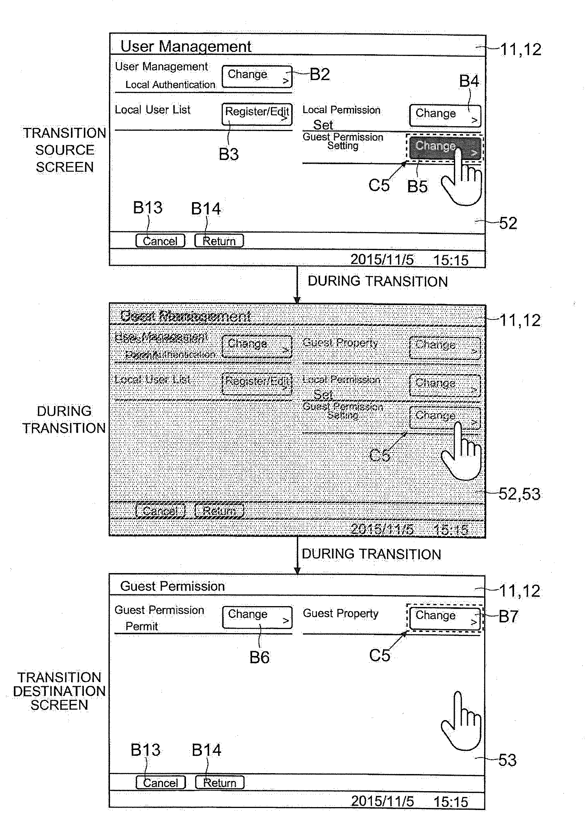
[0047]An embodiment of the present disclosure is described with reference to FIGS. 1 to 35. Here, although the present disclosure can be applied to various types of display input devices, there is exemplified and described an operation panel 1 (corresponding to the display input device) included in a multifunction peripheral 100 (corresponding to the image forming apparatus). However, elements such as structures and layouts described in this embodiment do not limit the scope of the disclosure and are merely examples for description.

[0048](Schematic Structure of Multifunction Peripheral 100)

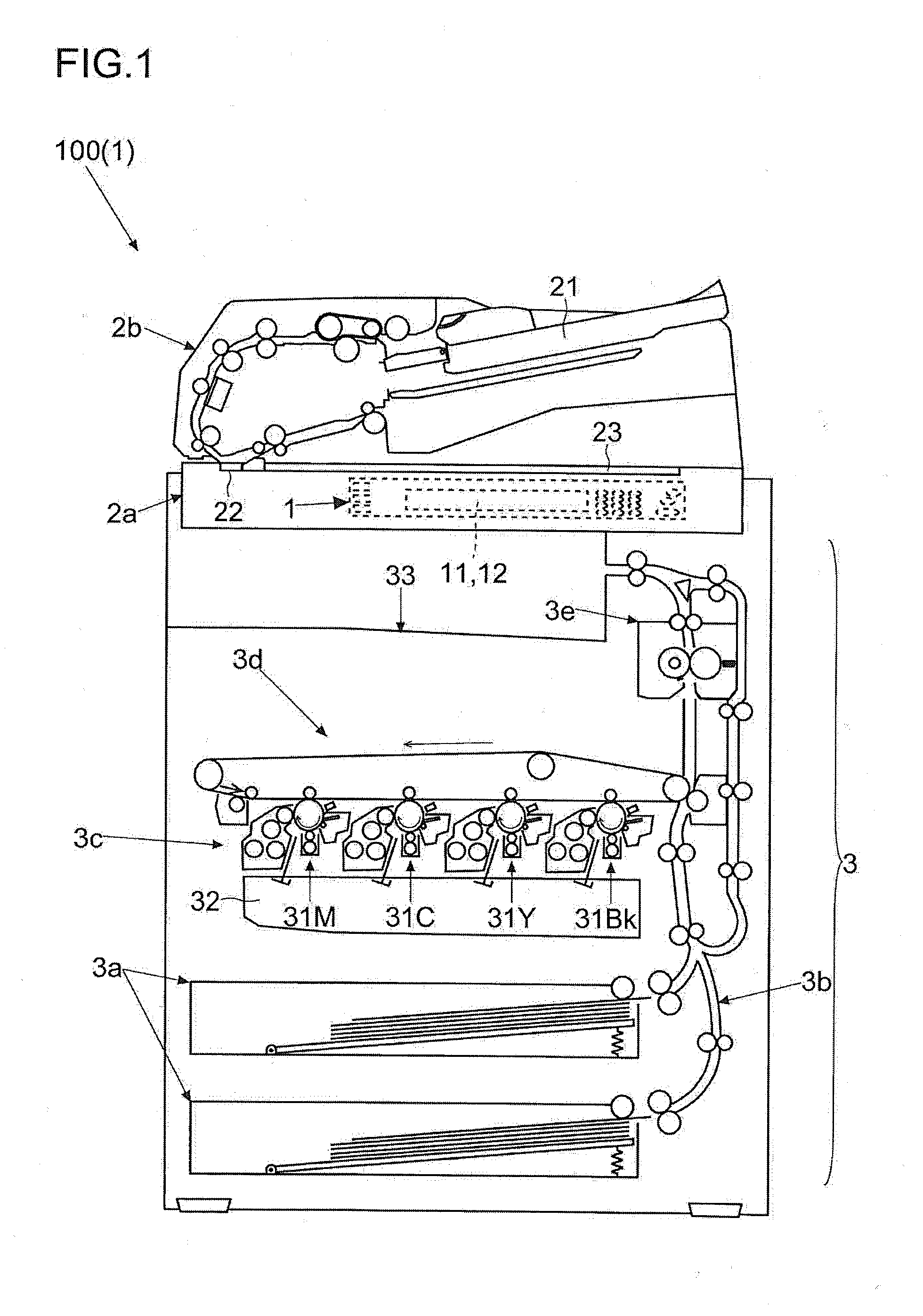
[0049]First, with reference to FIG. 1, a schematic structure of a main body of the multifunction peripheral 100 according to the embodiment is described.

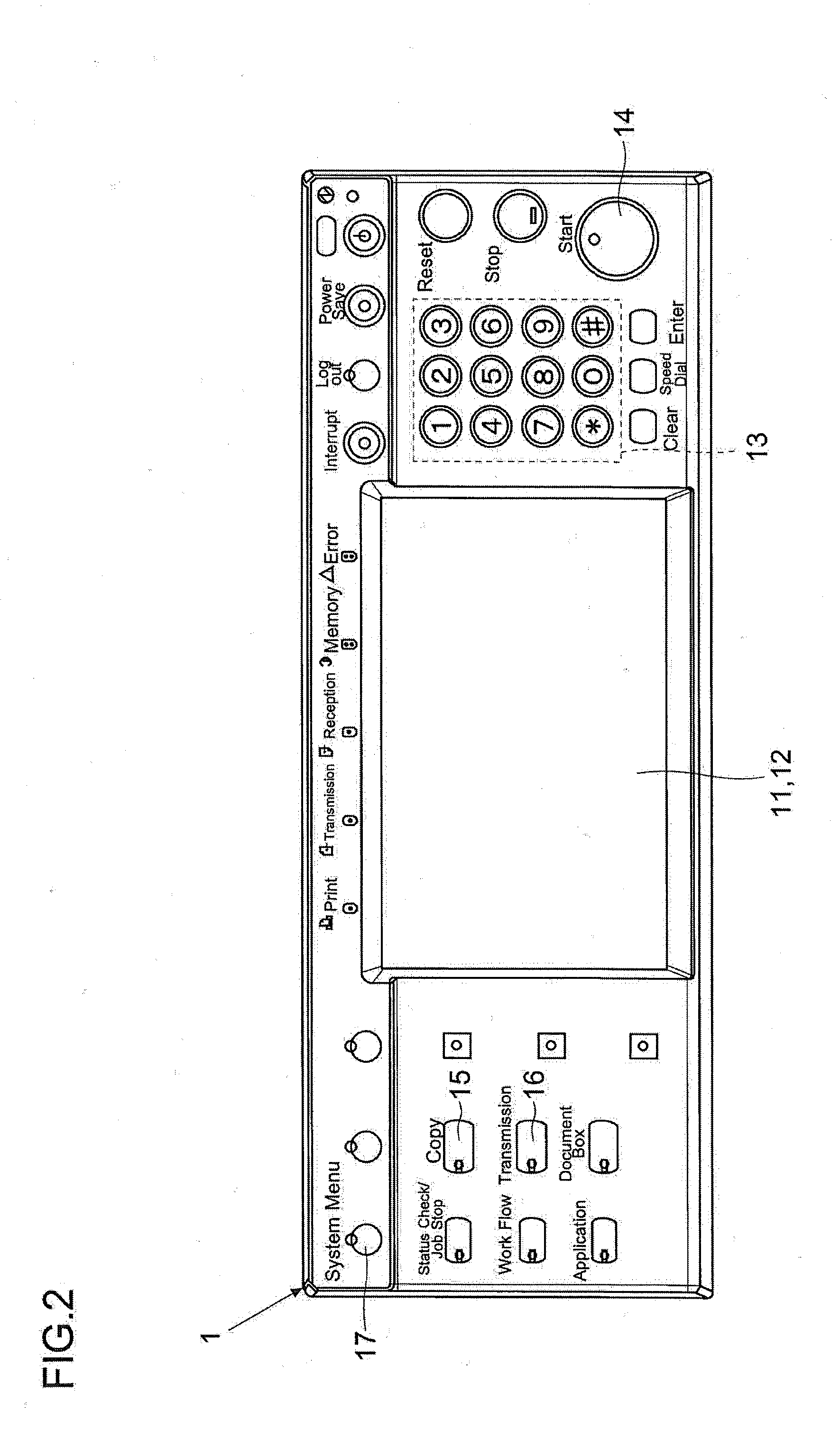
[0050]On an upper part of the multifunction peripheral 100 of this embodiment, there are disposed an image reader unit 2a, a document feeder unit 2b, and the operation panel 1 (details of the operation panel 1 is described later). The document fee...


PUM


Abstract

A display input device includes a display unit and a touch panel unit. When the touch panel unit accepts a predetermined transmission start operation, the display unit starts a display in a transmission transition mode, performs a transmission transition display in which a transition source screen gradually disappears while a ratio of a display of a transition destination screen belonging to a next lower layer of the transition source screen as time passes, and repeats the transmission transition display toward a lower layer.

Description

[0001]This application is based upon and claims the benefit of priority from the corresponding Japanese Patent Applications (1) No. 2013-225279 filed Oct. 30, 2013, (2) No. 2013-225563 filed Oct. 30, 2013, (3) No. 2013-245342 filed Nov. 27, 2013, and (4) No. 2013-245349 filed Nov. 27, 2013, the entire contents of which are incorporated herein by reference.BACKGROUND OF THE INVENTION[0002]The present disclosure relates to a display input device including a display unit and a touch panel.[0003]For instance, a display input device for inputting various settings via a screen may be attached to an apparatus or equipment. Further, as to a mobile phone terminal or the like, the number of hardware keys that can be disposed thereon is limited. Therefore, a plurality of roles (meanings) may be assigned to one key. Therefore, an input error may be caused because a user does not know a role (process) assigned to the current state of a key. In order to prevent such a decrease of operability, the...

Claims


Application Information

Patent Timeline
IPC IPC(8): H04N1/00G06F3/0488G06F3/0482G06F3/041G06F3/0484
CPCH04N1/00424G06F3/0416H04N1/00392G06F3/0482G06F3/04883G06F3/04842G06F3/0488G06F2203/04808H04N1/0035H04N1/00408H04N1/00411H04N1/00466H04N1/0049
Inventor NAKAGAWA, HIROSHIKODA, ISAOSETO, AKIFUMITAKAI, KENJISHIMIZU, TAKEO
Owner KYOCERA DOCUMENT SOLUTIONS INC
Why Eureka
Eureka Blog
Learn More