
Compact integrated touch panel display for a handheld device

a handheld device and touch panel technology, applied in the field of touch panel displays, can solve the problems of reducing the overall thickness reducing the size of the handheld device, and losing the proportion of the perimeter of the typical touch panel display used in the handheld device, so as to reduce the length of the bus traces used, reduce the size of the handheld device, and reduce the overall thickness.

Inactive Publication Date: 2005-11-15
QUALCOMM INC
View PDF13 Cites 243 Cited by
  • Summary
  • Abstract
  • Description
  • Claims
  • Application Information

AI Technical Summary

Benefits of technology

[0013]Accordingly, several embodiments of the present invention include structures that enable particular reductions in the overall dimensions of handheld devices. For example, the elimination of a bezel provides a direct decrease in height of the device. Further, the elimination of the bezel enables a reduction in the width and length of a handheld device. Another embodiment of the invention enables the length or width of the touch panel display to establish the maximum width and length of the underlying portion of a handheld device. Another aspect of the invention enables the aforementioned reductions in dimensions without impairing the visual characteristics of the touch panel display.
[0016]In still another embodiment of the invention, distributed local electrical connections are made between the touch panel display and the handheld device, thereby minimizing the length of bus traces used on the touch panel display.
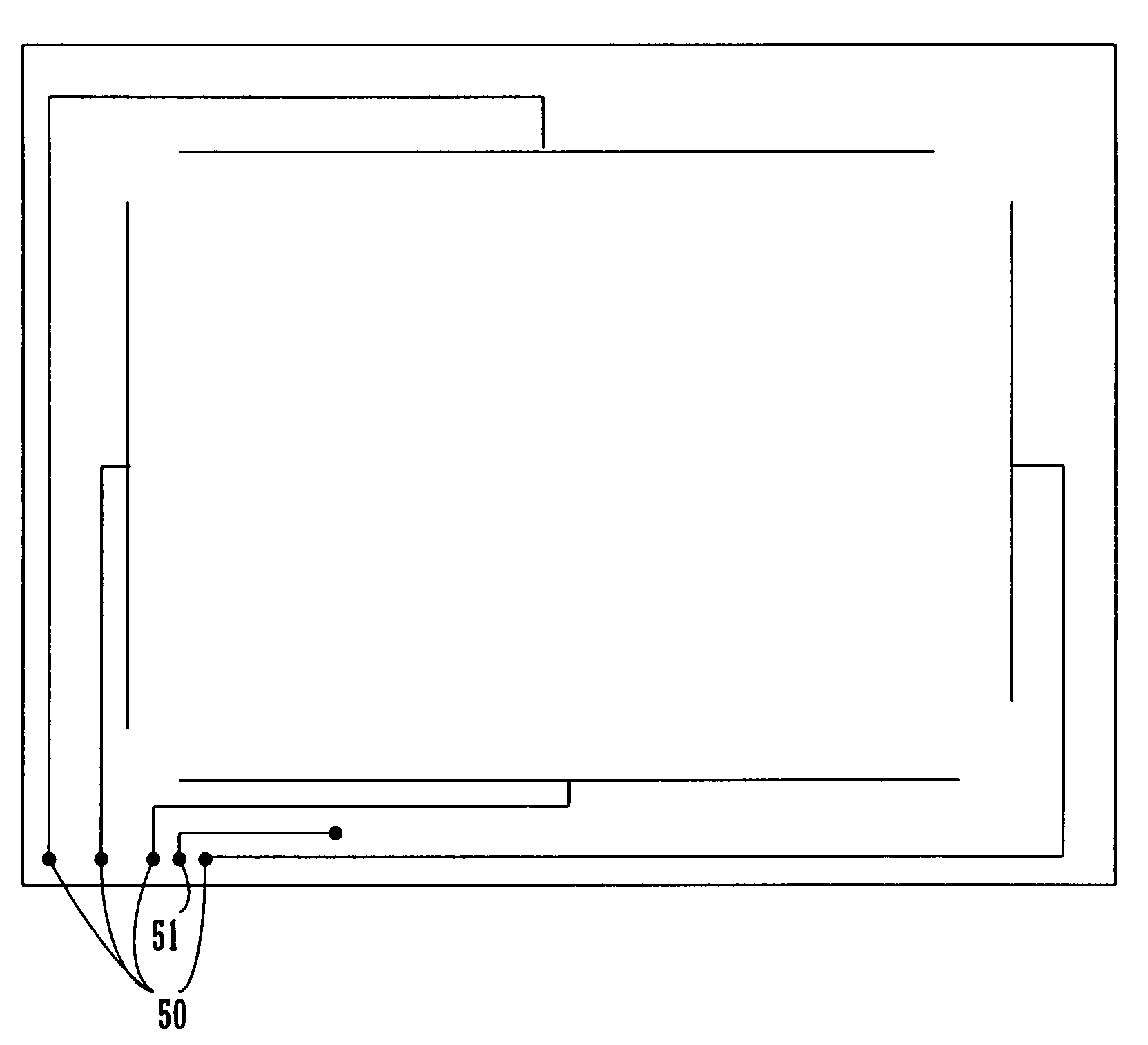
[0017]The embodiments described herein enable the reduction in size of a handheld device having a touch panel display. This reduction in size is achieved by incorporating electrical pathways within the support structure of the touch panel display, obviating the need for a flex circuit extension from the touch panel display for connection to the handheld device. A further reduction in size is obtained by providing an inherent visually homogeneous perimeter for the touch panel display by matching the colors of the conductive and dielectric materials, thereby eliminating the need for a bezel.

Problems solved by technology

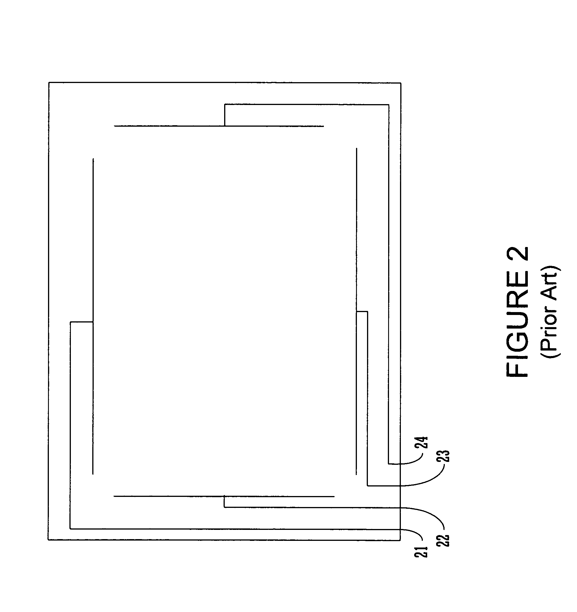
In spite of the fact that it is desirable to maximize the area available for touch panel displays, a portion of the perimeter of typical touch panel displays used in handheld devices is lost due to the manner in which they are integrated into the handheld device.
The geometry and coloration of the conductive and dielectric materials are such that they are typically visually non-homogeneous and require masking by the bezel.
However, the use of a bezel dictates an unwanted increase in the overall thickness of the handheld device over that which could be obtained for a flush-mounted touch panel display, and may also contribute to an increase in the length and width as well.

Method used


Image

  • Compact integrated touch panel display for a handheld device
  • Compact integrated touch panel display for a handheld device
  • Compact integrated touch panel display for a handheld device

Examples


Embodiment Construction

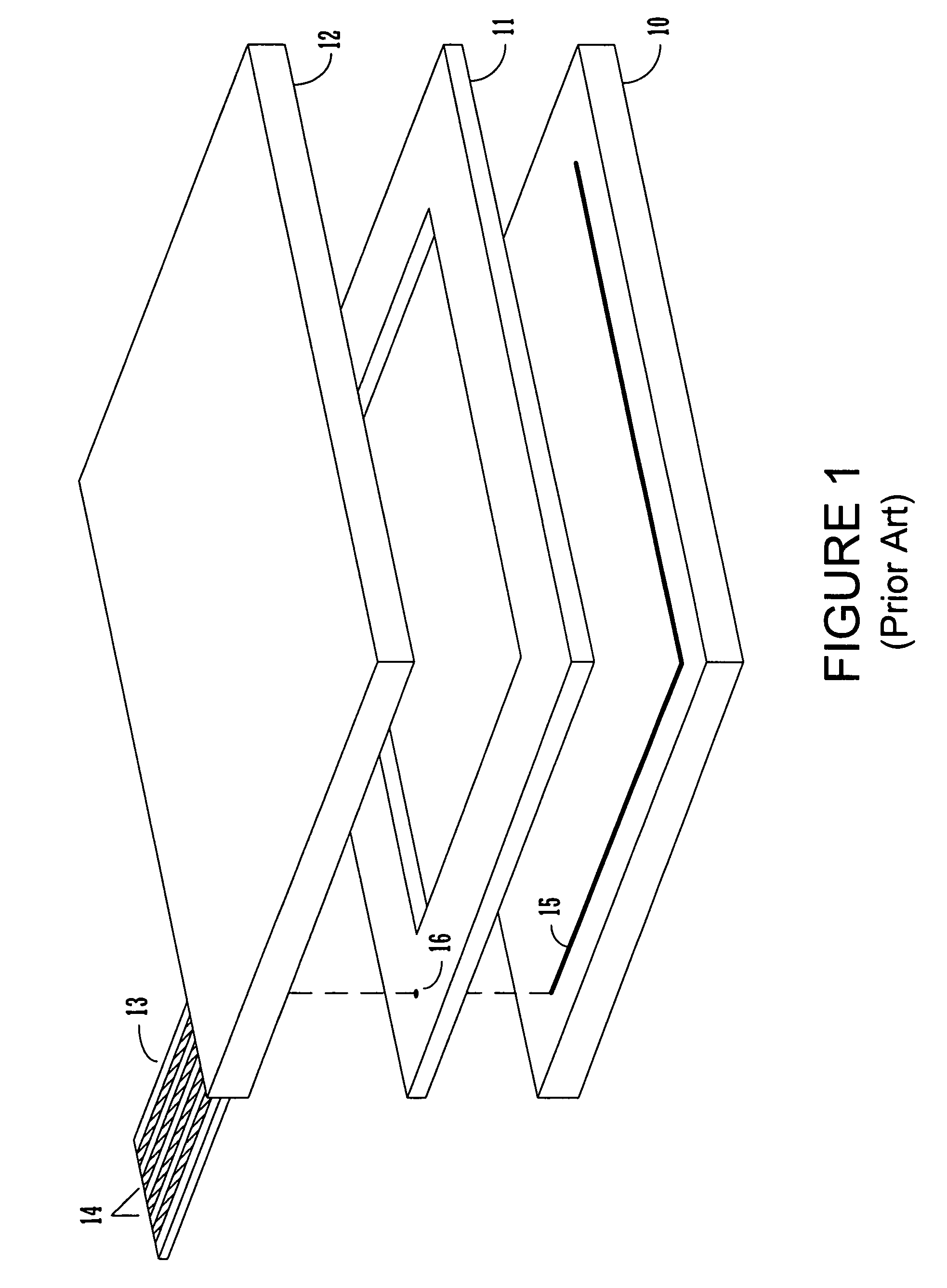
[0028]An exploded schematic view of a representative resistive touch screen with film-on-glass is shown in FIG. 1. A lower contact electrode 10 is separated from an upper contact electrode 12 by an adhesive dielectric spacer 11. The lower contact electrode 10 is constructed of a glass substrate with a transparent conductive coating of indium tin oxide (ITO). The adhesive dielectric spacer 11 serves to bond electrodes 10 and 12 together while maintaining electrical isolation between the two electrodes. The upper contact electrode 12 is constructed from a polyester film having a transparent conductive ITO coating on its lower surface as well as a low resistance conductive bus pattern.

[0029]A flex circuit tail 13 is attached to the upper contact electrode 12. The flex circuit tail 13 has a plurality of embedded conductors 14. It should be noted that the flex circuit tail is a feature common to many touch panel technologies in addition to the representative resistive touch panel shown i...


PUM


Abstract

A handheld device with a compact integrated touch panel is disclosed. A handheld device incorporating a touch panel display requiring electrical connections is reduced in size by incorporating electrical pathways within the support structure of the touch panel display, obviating the need for a flex circuit extension from the touch panel display for connection to the handheld device. A further reduction in size is obtained by providing an inherent visually homogeneous perimeter for the touch panel display by matching the colors of the conductive and dielectric materials, thereby eliminating the need for a bezel.

Description

FIELD OF THE INVENTION[0001]The present claimed invention relates to the field of touch panel displays. More particularly, the present claimed invention relates to touch panel displays that may be used for handheld devices.BACKGROUND ART[0002]Over the years, many electronic instruments and devices and been sufficiently reduced in size to become portable, and in turn, small enough to be held and operated in the hand of the user. The advent of integrated circuits greatly increased the number of devices that could achieve portability and handheld status, as well as increasing the functionality of such devices.[0003]Earlier handheld devices such as measuring instruments or electronic calculators had minimal requirements for display capability and much of the available area on the package of the device was dedicated to controls such as knobs and buttons, or a keypad. For such instruments, a display capable of handling up to a dozen or so alphanumeric characters was sufficient.[0004]As th...

Claims


Application Information

Patent Timeline
IPC IPC(8): G09G5/00G06F3/041G06F3/045
CPCG06F3/0412G06F3/045
Inventor GETTEMY, SHAWNNGUYEN, HUY P.WEBB, BILLLAM, LAWRENCEWONG, KEAN
Owner QUALCOMM INC
Learn More