Disposable surgical devices

Inactive Publication Date: 2005-02-01
ATL TECH LLC
View PDF5 Cites 134 Cited by
  • Summary
  • Abstract
  • Description
  • Claims
  • Application Information

AI Technical Summary

Benefits of technology

The present invention has been accomplished to provide disposable surgical devices, which eliminate the aforesaid drawbacks. It is therefore the main object of the present invention to provide disposable surgical devices, which consume less time and labor. It is another object of the present invention to provide disposable surgical devices, which are easy and inexpensive to manufacture. It is still another object of the present invention to provide a smart block technology to combine the major component requirements of disposable surgical devices into a single connector interface. It is still another object of the present invention to provide a smart block for disposable surgi

Problems solved by technology

This assembly process is time consuming and costly.2. The installation of the circuit board 35 in the electric wires 36 is time and labor consuming, resulting in high manufac

Method used


Image

  • Disposable surgical devices
  • Disposable surgical devices
  • Disposable surgical devices

Examples


first embodiment

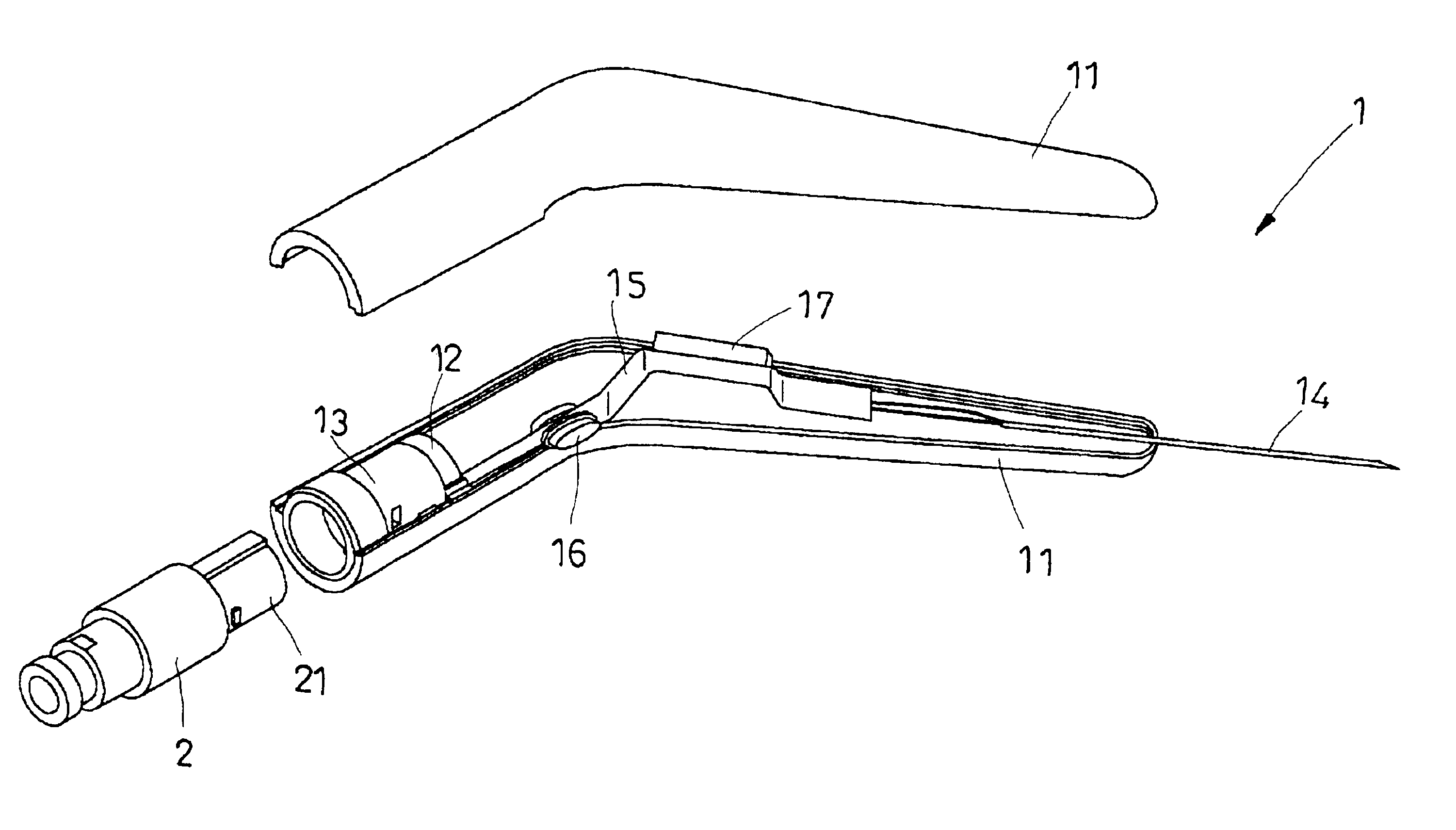
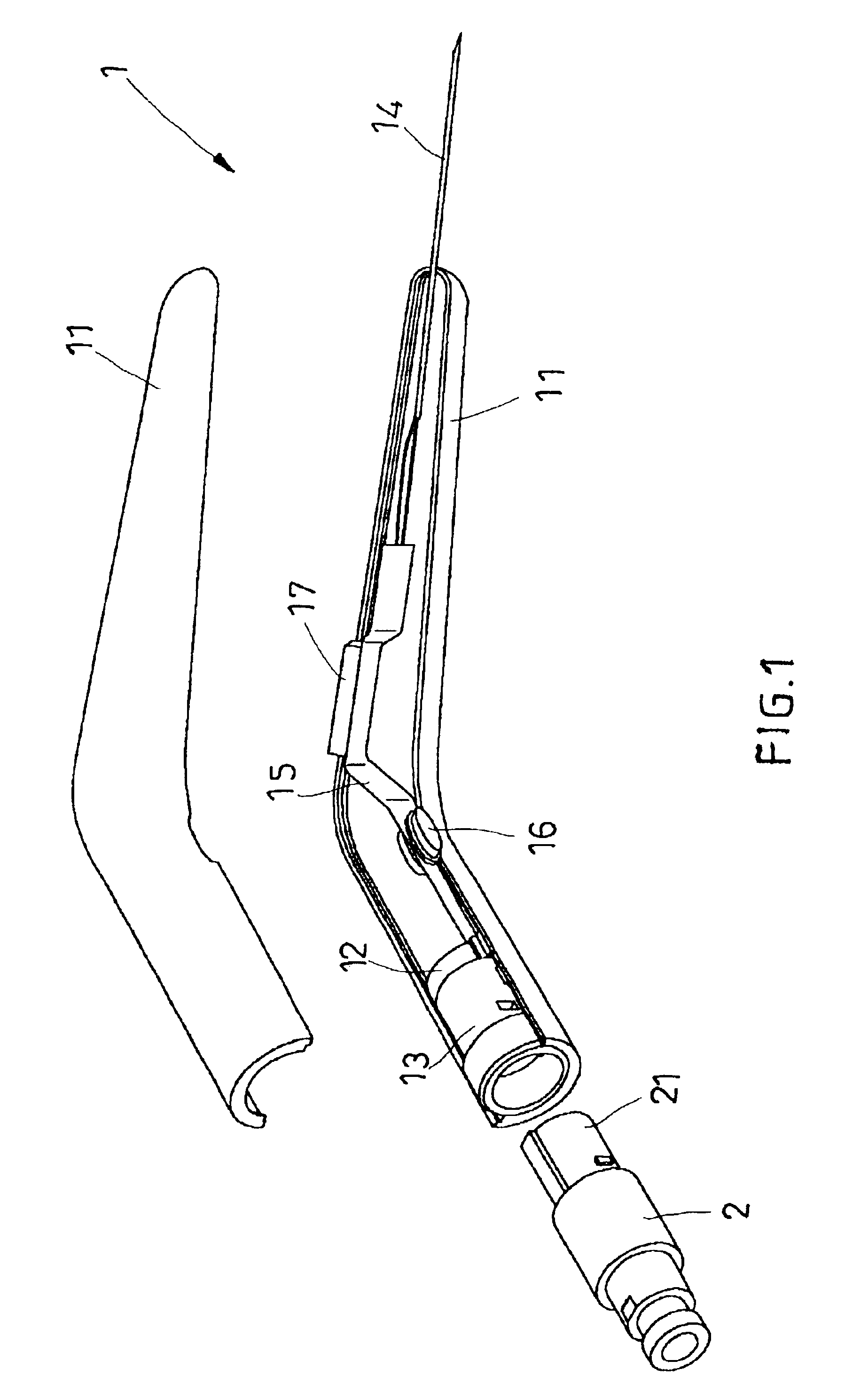
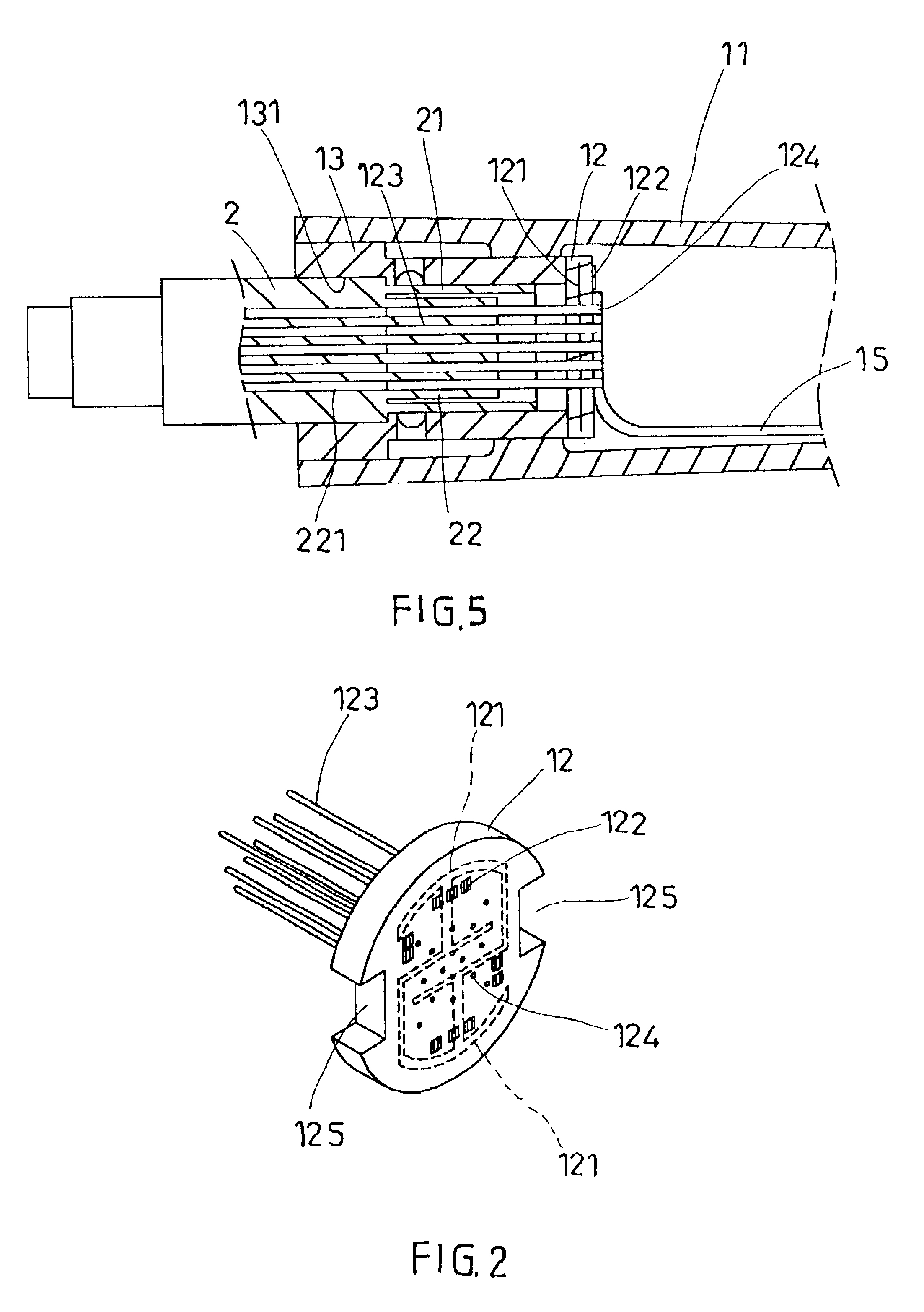
Referring to FIGS. from 1 through 4, a disposable surgical device 1 in accordance with the present invention is shown comprised of a shell (housing) 11, a smart block 12, an industry standard socket 13, a medical treatment terminal, for example, a surgical tip 14, and a flex circuit termination 15 connected between the smart block 12 and the surgical tip 14. The smart block 12 is provided inside the shell 11 near its rear end, having a circuit 121 embedded therein and electronic components 122 mounted to the circuit 121 subject to the surgery or treatments to be performed. A plurality of metal contact pins 123 are provided at one side of the smart block 12 for insertion into respective contact holes 221 in the connector 22 in the plug end 21 of an industry standard connector interface 2 to electrically connect the industry standard connector interface 2 to the circuit 121 of the smart block 12. The smart block 12 further comprises a plurality of wire terminal points (solder points) ...

second embodiment

FIGS. 6 and 7 show the present invention. According to this embodiment, electric wires 18 are provided to connect particular wire terminal points (solder points) 124 of the smart block 12 and the surgical tip 14 for transmission of high electric current, and the rest wire terminal points (solder points) 124 of the smart block 12 are respectively soldered to the corresponding wire terminal points (solder points) of the conductor lines 151 of the flex circuit termination 15.

third embodiment

FIGS. 8 and 9 show the present invention. According to this embodiment, electric wires 18 are installed in the smart block 12 and electrically connected between the wire terminal points (solder points) 124 of the smart block 12 and the surgical tip 14, i.e., all the wire terminal points (solder points) 124 of the smart block 12 are electrically connected to the surgical tip 14 by the electric wires 18 respectively for the transmission of high electric current.

A prototype of disposable surgical device has been constructed with the features of FIGS. 1˜9. The disposable surgical device functions smoothly to provide all of the features discussed earlier.


PUM


Abstract

A disposable surgical device is constructed to include a shell, a smart block mounted in one end of the shell, the smart block electronic having components mounted to a circuit embedded therein, front contact pins for insertion into respective contact holes in the connector of an industry standard connector interface, and rear wire terminal points, a medical treatment terminal installed in the other side of the shell and adapted for performing surgery and treatments, and a flex circuit termination electrically connected between the smart block and the medical treatment terminal, the flex circuit termination having embedded conductor lines respectively connected to the medical treatment terminal and wire terminal points at the ends of the conductor lines respectively soldered to the wire terminal points of the smart block.

Description

BACKGROUND OF THE INVENTION1. Field of the InventionThe present invention relates to disposable surgical devices for use with a medical apparatus to perform invasive surgery and treatments and, more particularly, to such disposable surgical devices that are easy and inexpensive to manufacture.2. Description of the Related ArtThe medical industry uses RF energy to perform invasive surgery and treatments. These procedures are performed through the use of disposable surgical devices. FIGS. 10˜12 show a prior art disposable surgical device 3 for this purpose. This structure of disposable surgical device 3 comprises a shell (housing) 31, a connection block 32, a medical treatment terminal, for example, a surgical tip 33, a switch 34, a circuit board 35, and electric wires 36 connecting the parts. The connection block 32 comprises a plurality of forwardly extended contact pins 231 for connecting to an industry standard connector interface 2. The contact pins 231 each have a tubular rear e...

Claims


Application Information

Patent Timeline
IPC IPC(8): A61B18/14
CPCA61B18/14A61B2018/00178
Inventor CHEN, PAUL FEI-TALEVANTE, JAMES JOHNNGUYEN, CHUONG DINH
Owner ATL TECH LLC
Why Eureka
Try Eureka