Input device and electronic device using the input device

Inactive Publication Date: 2007-04-12
SONY CORP
View PDF5 Cites 244 Cited by
  • Summary
  • Abstract
  • Description
  • Claims
  • Application Information

AI Technical Summary

Benefits of technology

[0011] With the above configuration, the vibration generation device generates various forms of vibrations in accordance with the type of information under the control of the vibration control circuit. As a result, when the user performs input operation by touching the touch panel, the vibration generated in accordance with the type of information can be fed back to the user through the sense of touch. The tactual feedback is similar to “click sense” or “stroke sense” that has been widely used as a feedback to the operation and is advantageous for the user in that it is more intuitive than a feedback due to images or sounds. Further, each of the first and second actuator units included in the bimorph piezoelectric actuator is constituted by multi-layered piezoelectric element layer. Such a laminated piezoelectric actuator can cause greater deflection (bending) displacement in the vibration direction as compared to the case where each of the first and second actuator units is constituted by a single piezoelectric element layer.
[0012] The present invention is the input device and an electronic apparatus using the input device, the input device further including an image display unit that displays information. The user can perform the input operation of information by touching a portion on the touch panel corresponding t

Problems solved by technology

In the case where a small electronic apparatus such as a PDA, to which the feedback system realized by the method of changing images or sounds is applied, is used outdoor, it may be difficult to sufficiently convey a feedback due to ambient noise or darkness.
In addition, when the user points an icon or the like on the display window with a finger, the image may be covered by the finger, so that feedback information

Method used


Image

  • Input device and electronic device using the input device
  • Input device and electronic device using the input device
  • Input device and electronic device using the input device

Examples


Embodiment Construction

[0030] Preferred embodiments of the present invention will be described below with reference to the accompanying drawings. Incidentally, since the embodiments described below are preferred specific examples of the present invention, technically preferred various limitations are added. However, the scope of the invention is not limited to these embodiments as long as the following description does not contain recitation to specifically limit the invention.

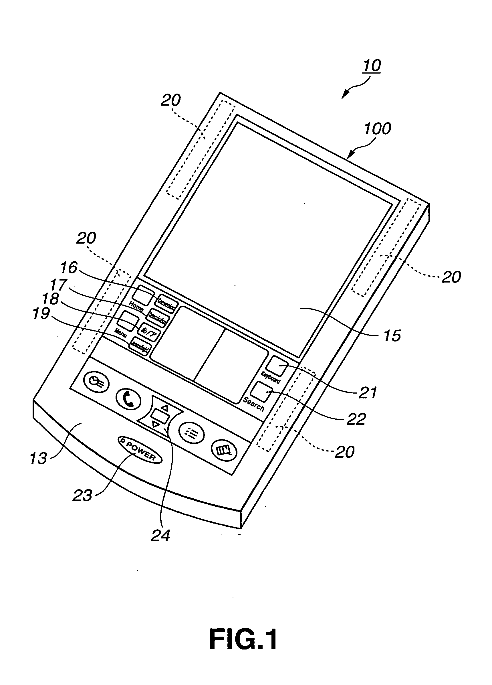
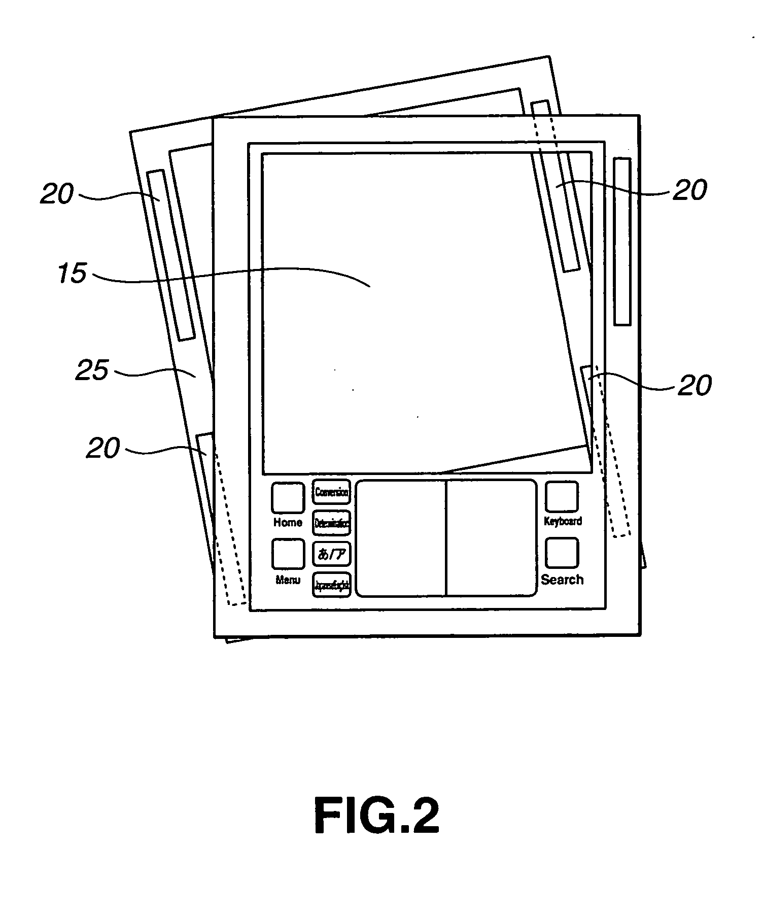
[0031] An electronic apparatus 10 provided with an input / output device according to the present invention is a PDA (Personal Digital Assistant) having the configuration as shown in FIG. 1.

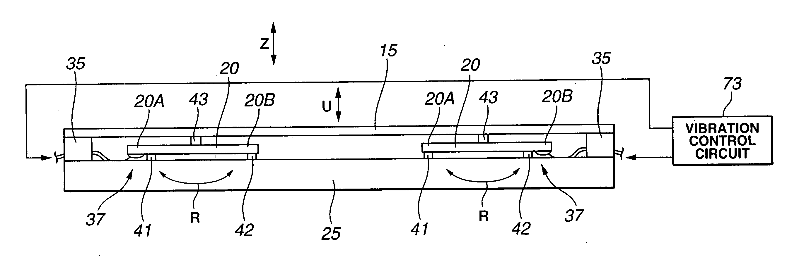
[0032] In the PDA serving as the electronic apparatus according to the present invention, a tactual feedback generation function using the sense of touch (vibration) is added to the touch panel, so that a feedback to input operation performed in accordance with the type of information can be offered to the user through the sense of touch. The tac...


PUM


Abstract

The present invention related to an input device including: an image display unit (30) that displays information; a touch panel (15) with which a user performs input operation of information by touching a portion corresponding to the position at which the information of the image display unit is displayed; a vibration generation device (71) disposed in the image display unit and feeds back, to the user, various kinds of sense of touch in accordance with the type of the information through the touch panel; and a vibration control circuit (73) for allowing the vibration generation device to generate various forms of vibrations in accordance with the type of the information. The vibration generation device is a bimorph piezoelectric actuator. Each of first and second actuator units has multi-layered piezoelectric elements (63). By this way, it is possible to provide an input/output device capable of surely realizing a feedback to user's input operation performed in accordance with the type of information through the sense of touch when the user performs an input operation of information to a touch panel using the sense of touch.

Description

TECHNICAL FIELD [0001] The present invention relates to an input device and an electronic apparatus using the same capable of realizing a feedback to user's input operation through the sense of touch when the user performs an input operation of information by touching a touch panel. [0002] This application claims priority of Japanese Patent Application No. 2002-251781, filed on Aug. 29, 2002, the entirety of which is incorporated by reference herein. BACKGROUND ART [0003] For example, an ATM (Automated Teller Machine) is here taken as an example of the electronic apparatus. A touch panel is attached to the display surface of the ATM. In the operation using the ATM, a user inputs -information through the touch panel, and a feedback to user's input operation is realized by a device added to the outside of the ATM. The added device realizes the feedback by changing images on the display window of the ATM or by changing sounds using a speaker or sounder. [0004] In the case where a small...

Claims


Application Information

Patent Timeline
IPC IPC(8): G09G5/00G06F3/041G06F1/16G06F3/00G06F3/01H01H9/16H01H13/712
CPCG06F1/1626G06F1/1637H01H2215/052G06F2203/014H01H2215/028G06F3/016H03K2217/96015H03K2217/960755
Inventor MARUYAMA, SHIGEAKIMOTOYAMA, SHIGEKIPOUPYREV, IVANKIMURA, KEIICHI
Owner SONY CORP
Why Eureka
Try Eureka