
Electronic hearing protector with quadrant sound localization

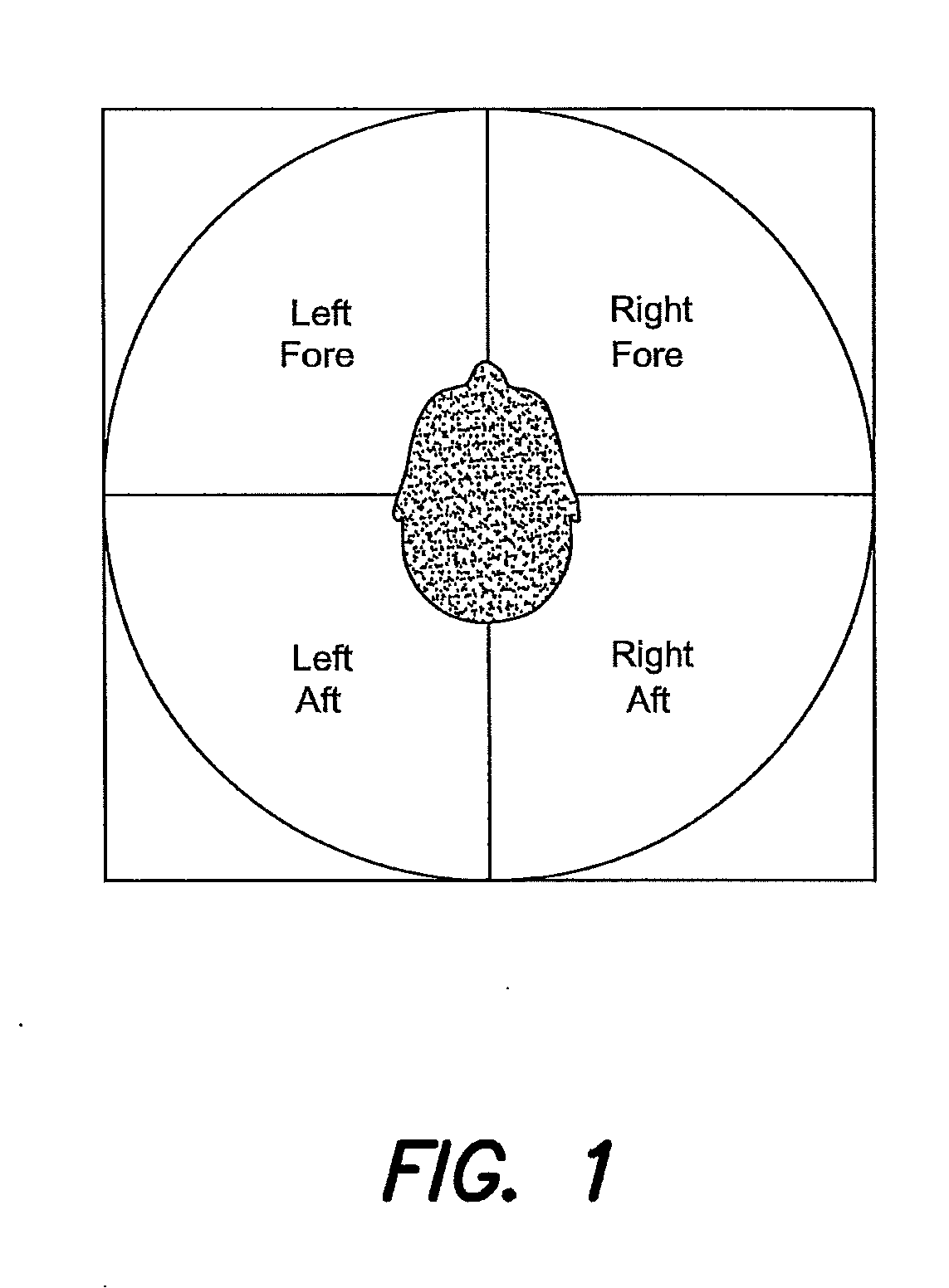
a quadrant sound and hearing protection technology, applied in the field of electro-optical hearing protection, can solve the problems of insufficient duplex theory for front-to-back sound localization, inability to recreate the correct spatial sensation for a different listener, and similar ambiguity, and achieve the effect of facilitating sound localization

Active Publication Date: 2015-04-30
HARMAN INT IND INC
View PDF3 Cites 16 Cited by
  • Summary
  • Abstract
  • Description
  • Claims
  • Application Information

AI Technical Summary

Benefits of technology

The patent describes an electronic hearing protector that allows users to hear sound more clearly and comfortably in noisy environments. The protector includes filters that process the signals from two microphones, and a processor that combines the two signals to provide a better representation of the sound. The result is an improved sound localization for the user. The protector can also include additional features such as notch filters or shelf filters to enhance the sound quality. Overall, the technical effect of the patent is to provide a superior electronic hearing protection solution.

Problems solved by technology

In fact, shifting the sound source 30 degrees to the left in both the front and rear would result in a similar ambiguity.
In other words, duplex theory is insufficient for front-to-back localization of sound, and also for localization in elevation.
However, since HRTFs vary from person to person, a given HRTF measured and encoded for one listener may not always recreate a the correct spatial sensation for a different listener.
However, the use of headphones still alters the listener's HRTF since normal pinna filtering is bypassed when a microphone is placed on the outside of the hearing protection ear cup.

Method used


Image

  • Electronic hearing protector with quadrant sound localization
  • Electronic hearing protector with quadrant sound localization
  • Electronic hearing protector with quadrant sound localization

Examples


Embodiment Construction

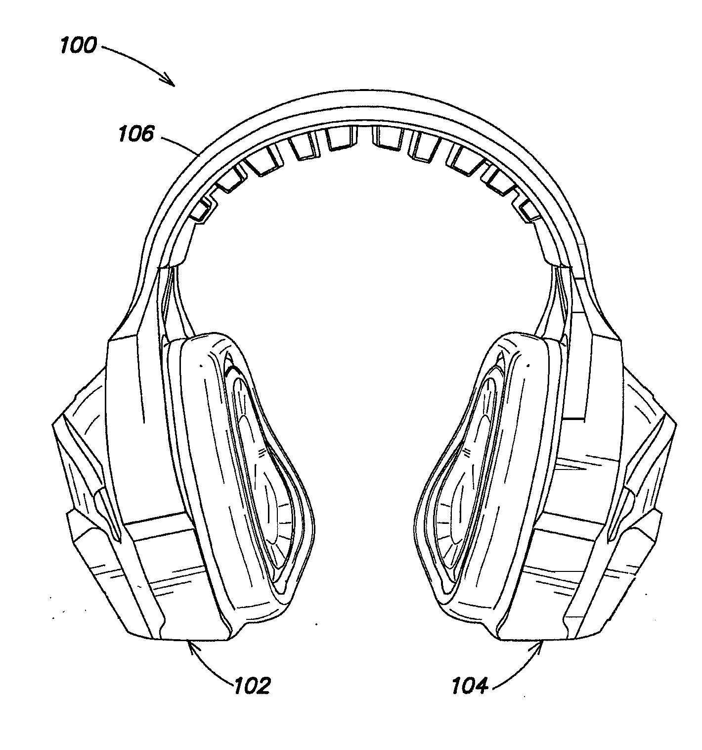
[0036]FIGS. 8A and 8B are perspective pictorial illustrations of an electronic hearing protector / headset 100, which includes a first ear cup assembly 102, a second ear cup assembly 104 and a head band 106 that interconnects the first and second ear cup assemblies 102, 104. The first ear cup assembly 102 includes a first front microphone assembly 107 and a first rear microphone assembly 108. The second ear cup assembly 104 includes a second front microphone assembly and a second rear microphone assembly (not shown). Each of the microphone assemblies may include an array microphone comprising a plurality of omnidirectional microphones. Alternatively, directional microphones may also be used.

[0037]FIG. 9 is a block diagram illustration of signal processing 110 associated with at least one of the ear cup assemblies 102, 104 (FIGS. 8A and 8B). The front microphone assembly provides a front microphone signal on a line 112 and the rear microphone assembly provides a rear microphone signal ...


PUM


Abstract

An electronic hearing protector includes an ear cup assembly comprising a front exterior microphone that provides a front microphone signal and a rear exterior microphone that provides a rear microphone signal. A processor receives and digitizes the front microphone signal and the rear microphone signal, and provides a front channel signal and a rear channel signal indicative thereof respectively. A filter receives the rear channel signal and has a cut-off frequency value that provides a high-frequency roll-off and a notch at a notch filter frequency value that is less than the cut-off frequency value, where the filter provides a filtered signal. A first signal indicative of the front channel signal and a second signal indicative of the filtered signal are summed, and a signal indicative of the summed signal is provided to a speaker within the ear cup that provides an audio signal within the first ear cup indicative of the summed signal.

Description

FIELD OF TECHNOLOGY[0001]The present disclosure relates to the field of electronic hearing protection, and in particular to electronic hearing protectors that include quadrant sound localization.RELATED ART[0002]Humans (and other animals) use two ears to localize sounds from left to right and from front to back. A sound source at a given angle will arrive at the closer ear earlier and typically at a stronger level, and will arrive at the farther ear later and typically at a weaker level. These binaural cues are known as the interaural time difference (ITD) and the interaural intensity difference (IID). When a sound source is directly in front of the listener, the levels and arrival times are equal.[0003]This simplification, referred to as “duplex theory”, allows for localization of sounds in the horizontal plane in front of the listener, but there remains some ambiguity if sounds from the rear are also of interest. For example, a sound originating from a point directly ahead of the ...

Claims


Application Information

Patent Timeline
Patent Type & Authority Applications(United States)
IPC IPC(8): A61F11/14
CPCA61F2011/145A61F11/14H04R1/1008H04R1/1083H04R3/005H04R5/027H04R5/033H04R2410/05A61F11/145
Inventor KIRSCH, JAMESHUTCHINGS, JEFFREY L.LAMBERT, RUSSELLHUNSAKER, JOSH
Owner HARMAN INT IND INC
Learn More