Method and apparatus for introducing an intraveneous catheter

a technology of intravenous catheter and catheter insert, which is applied in the direction of catheters, guide needles, other medical devices, etc., can solve the problem that the blood within the chamber is essentially inaccessible for collection and testing

Active Publication Date: 2015-04-30
WEXLER TOBY
View PDF16 Cites 41 Cited by
  • Summary
  • Abstract
  • Description
  • Claims
  • Application Information

AI Technical Summary

Benefits of technology

[0018]It is a further object of this invention to provide the ability to orient the beveled needle in a...

Problems solved by technology

However blood within the chamber is essen...

Method used


Image

  • Method and apparatus for introducing an intraveneous catheter
  • Method and apparatus for introducing an intraveneous catheter
  • Method and apparatus for introducing an intraveneous catheter

Examples


Embodiment Construction

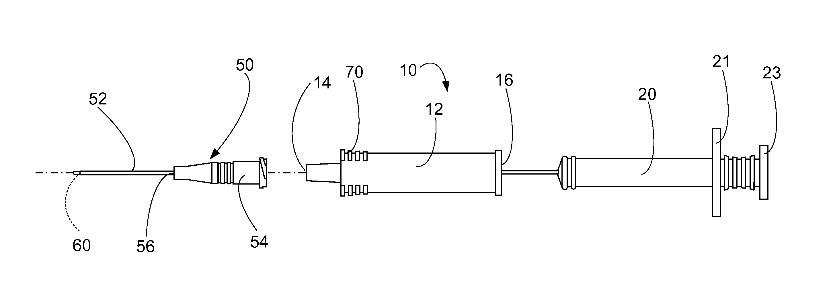
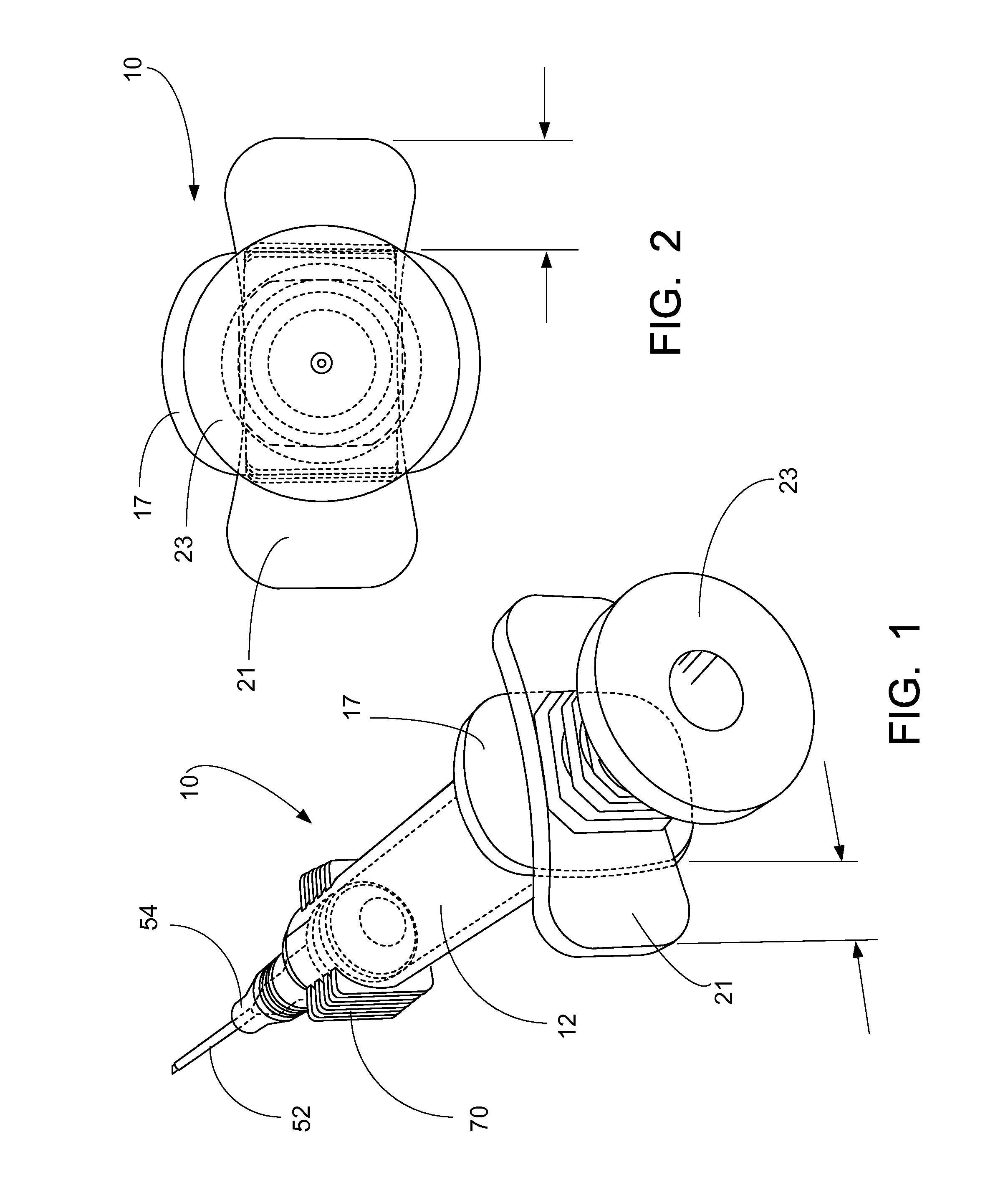
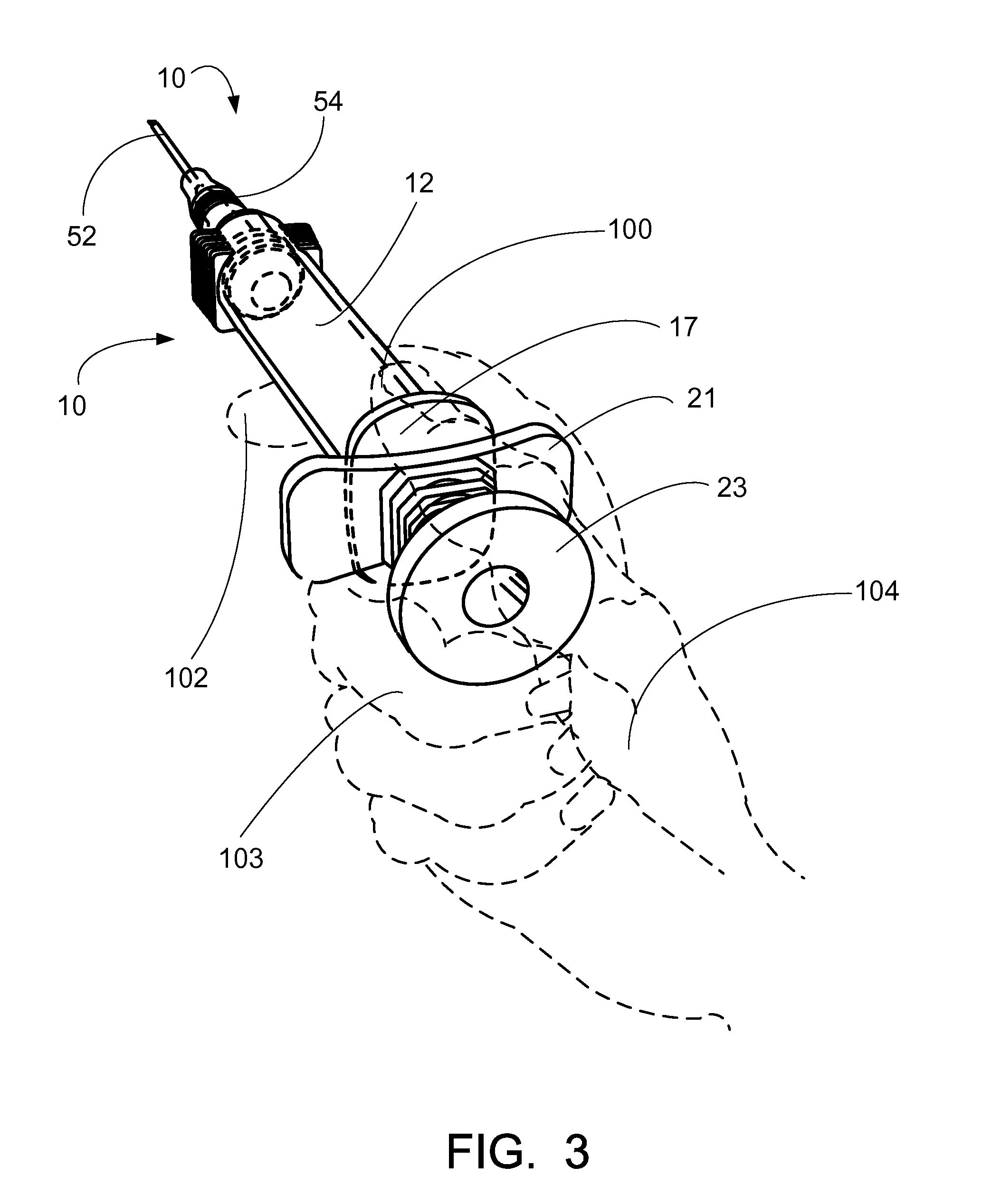
[0028]FIGS. 1-8 illustrate the preferred embodiment of the catheter insertion assembly of the present invention by the numeral 10. As illustrated in the figures, the assembly 10 would include a transparent tubular member 12 open at a first mammilated end 14 and a second end 16. There would be further provided a plunger assembly 20 slidable within chamber 23 within the tubular member 12, with the plunger assembly 20 having a continuous tubular chamber 22 and a vent 24 at the distal end 25 of the member 20. There is further provided, as seen in the drawings, at least a partially transparent chamber needle base 26 and a sealing member 28 on a second end 30 of the plunger assembly 20. As seen in the drawings there is included an elongated tubular needle 40 embedded within a needle base 26 and extending therefrom with the needle 40 in fluid communication with the transparent chamber 22 as seen in FIGS. 6A and 6B. The assembly 10 further includes a catheter assembly 50, having a transpare...


PUM


Abstract

An improved catheter insertion assembly having a transparent tubular member open at each end; a plunger assembly slidable within the tubular member having a stem portion at a first end; and at least a partially transparent chamber having a needle base and sealing member on a second end of the plunger assembly; an elongated tubular needle embedded within the needle base and extending there from with the needle in fluid communication with the transparent chamber; a catheter assembly, a transparent cannula and a transparent hub attached to the second end with the tubular needle passing longitudinally through the cannula; a fluid passage formed between the needle and the cannula so that when the plunger is retracted a vacuum is established within the fluid passage and blood is visibly drawn through the fluid passage into the transparent cannula and if volume permits, blood then would be visible in the transparent hub, and then if volume permits blood would be visible in the void of the catheter body (barrel) created by pulling the plunger; and wherein the tubular needle is threaded through a lumen of the cannula; and wherein the sealing member provides a sliding seal between the plunger assembly and the transparent tubular member; and wherein, a fluid communication exists through the needle into the flashback chamber of the plunger apparatus and through a porous vent. The distal end of the catheter device described herein has the addition of an external flange and dual plunger paddles which allow dynamic positioning of the fingers and one handed operation. Furthermore these structures are ergonomically associated to maximize finger surface area operation; and wherein the user can change the orientation of the beveled needle.

Description

CROSS-REFERENCE TO RELATED APPLICATIONS[0001]This is a nonprovisional patent application of U.S. Provisional Patent Application Ser. No. 61 / 753,776, filed 17 Jan. 2013, which is hereby incorporated herein by reference. Priority of U.S. Provisional Patent Application Ser. No. 61 / 753,776, filed 17 Jan. 2013, which is incorporated herein by reference, is hereby claimed.[0002]This application is related to U.S. Pat. No. 8,202,253, which issued on 19 Jun. 2012, entitled “Method and Apparatus for Introducing an Intravenous Catheter”, by the same inventor. U.S. Pat. No. 8,202,253, issued on 19 Jun. 2012, is hereby incorporated herein by reference.STATEMENT REGARDING FEDERALLY SPONSORED RESEARCH OR DEVELOPMENT[0003]Not applicableREFERENCE TO A “MICROFICHE APPENDIX”[0004]Not applicableBACKGROUND OF THE INVENTION[0005]1. Field of the Invention[0006]The present invention relates generally to methods and apparatus for introducing a peripheral Intravenous (I.V.) catheter into a subcutaneous bloo...

Claims


Application Information

Patent Timeline
IPC IPC(8): A61M25/06
CPCA61M25/0606A61M25/0693
Inventor WEXLER, TOBY
Owner WEXLER TOBY
Why Eureka
Try Eureka